Sealed prismatic battery

a prismatic battery and prismatic technology, applied in the direction of current conducting connection, wound/folded electrode electrode, cell components, etc., can solve the problems of short circuit of the current collector lead of the electrode, difficult welding of the current collector lead of the negative electrode to the lead plate, and obstructive sidewall of the insulator. , to achieve the effect of easy welding of the current collector

Inactive Publication Date: 2006-04-06
HITACHI MAXELL ENERGY LTD
View PDF0 Cites 56 Cited by
  • Summary
  • Abstract
  • Description
  • Claims
  • Application Information

AI Technical Summary

Benefits of technology

[0007] An object of the present invention is to provide a sealed prismatic battery capable of easily welding the current collector lead to the lead plate while preventing the current collector lead from being short-circuited with the lid or the sidewall of the battery can.

Problems solved by technology

Therefore, the negative electrode current collector lead is easily brought in contact with the inner surface of the battery can by the bending, and it is concerned that the negative electrode current collector lead is short-circuited with the battery can.
However, according to JP 2004-14395 A, the lead plate is also covered with the sidewall of an insulator, and the sidewall of the insulator becomes obstructive, making it difficult to weld the negative electrode current collector lead to the lead plate.
However, there is a problem that the negative electrode current collector lead is pinched between the upper end of the spacer and the lid in fitting the lid into the battery can, possibly causing a short circuit between the negative electrode current collector lead and the lid.

Method used


Image

  • Sealed prismatic battery
  • Sealed prismatic battery
  • Sealed prismatic battery

Examples


first embodiment

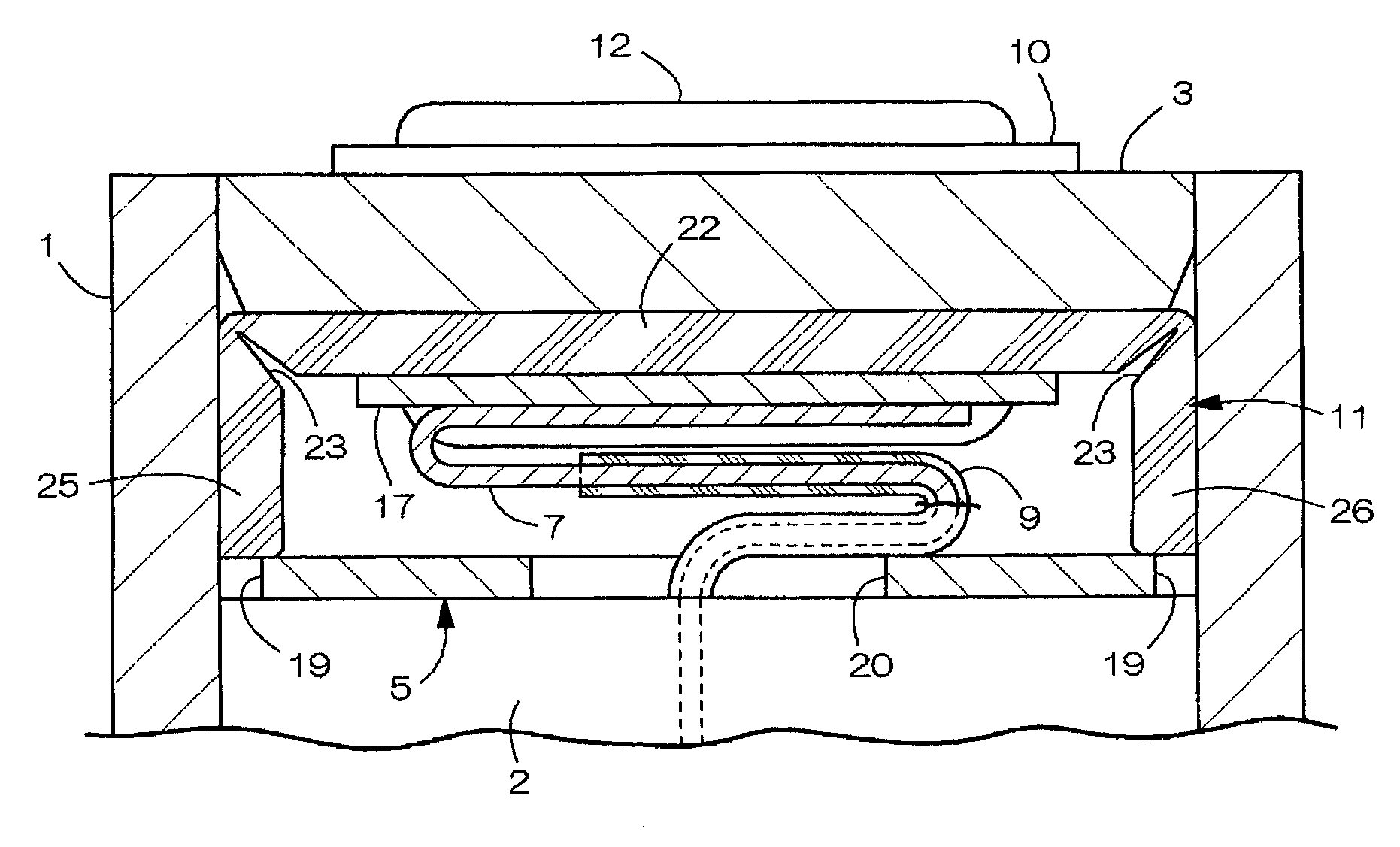
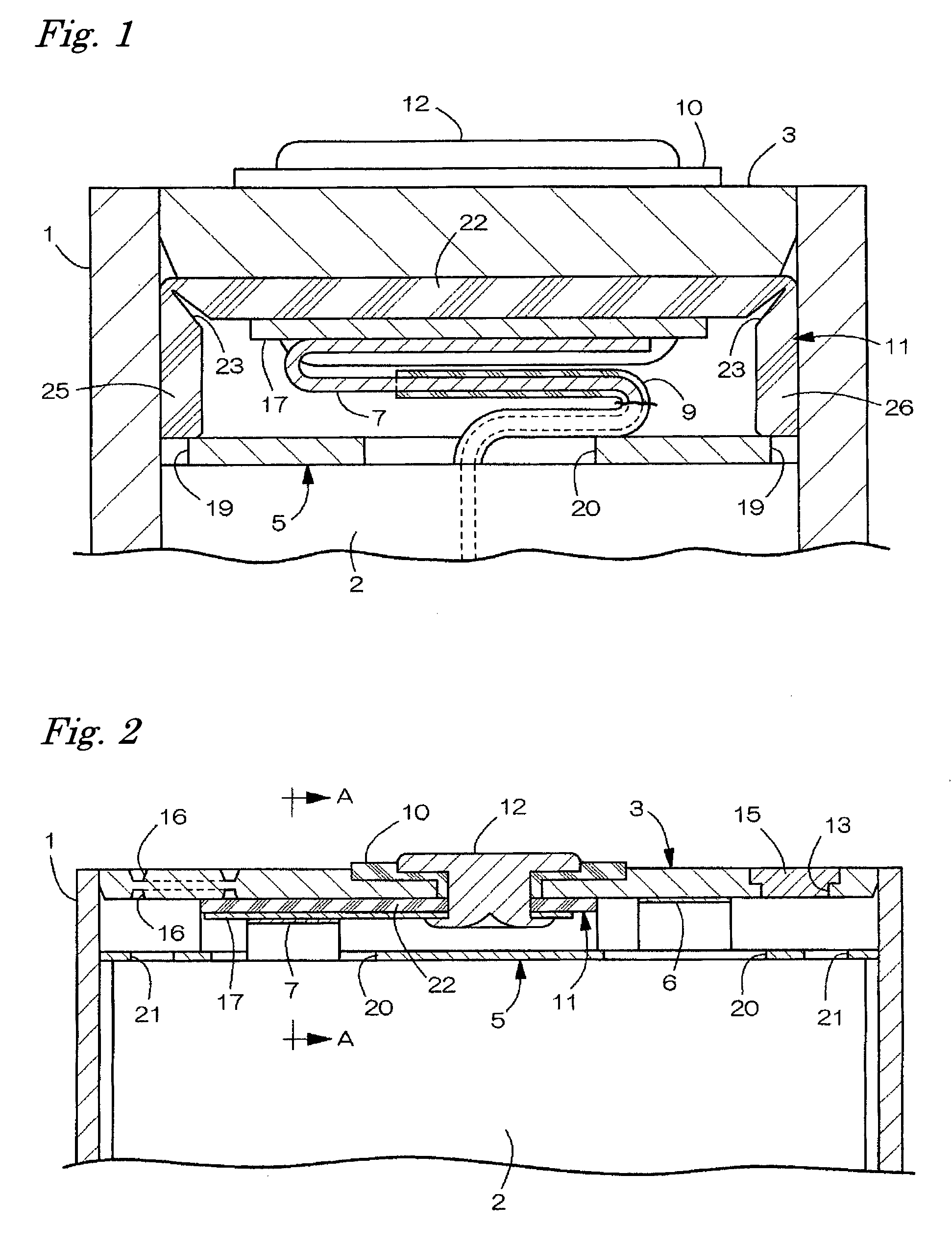
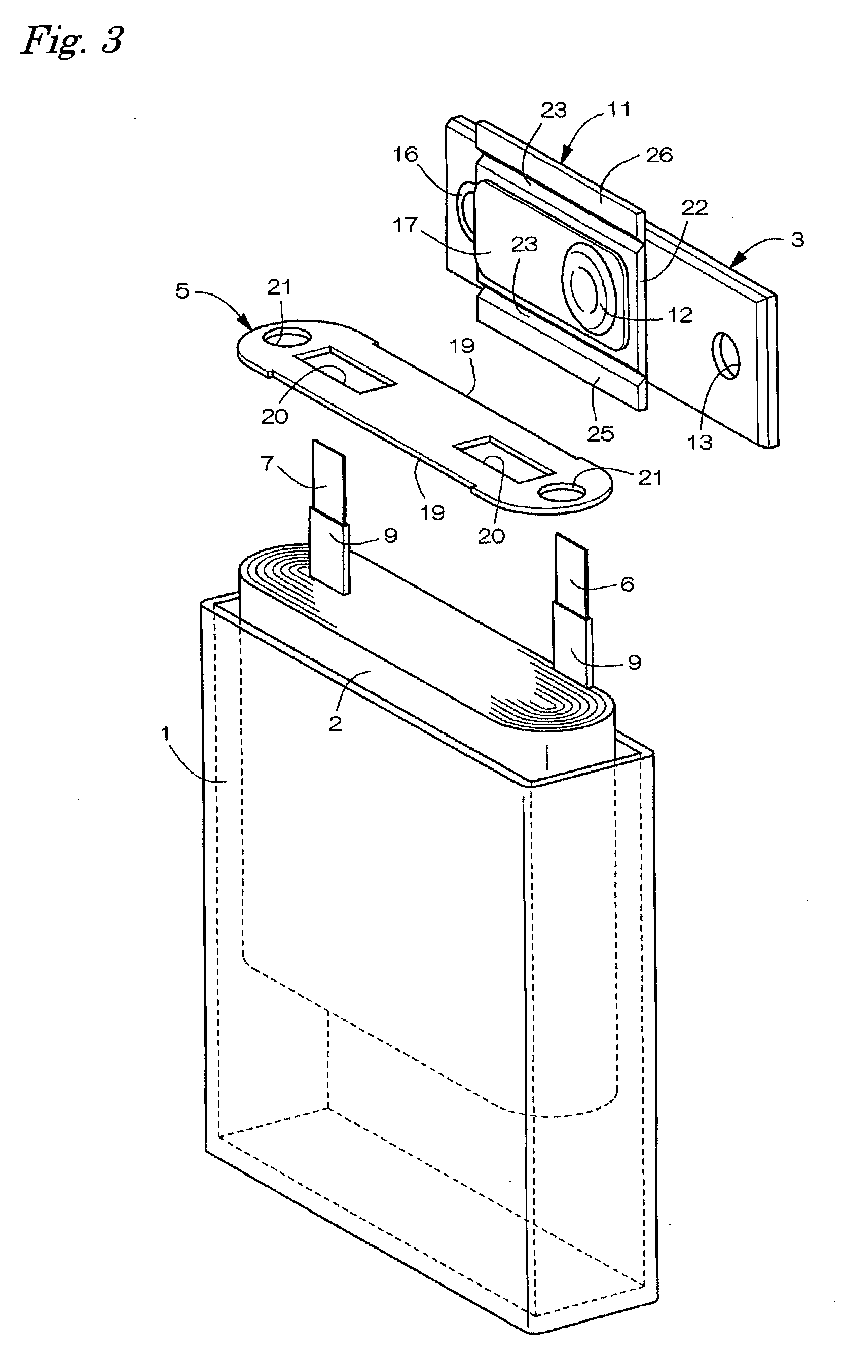
[0035]FIGS. 1 through 5 show the first embodiment of a lithium ion secondary battery as the sealed prismatic battery of the present invention. As shown in FIG. 3, the lithium ion secondary battery has a closed-bottom prismatic tubular battery can 1 that has a laterally elongated opening at its upper surface, an electrode body 2 and a nonaqueous electrolyte accommodated in the battery can 1, a laterally elongated lid 3 that closes the upper surface of the opening of the battery can 1, a thin-plate-shaped insulating plate 5 placed on the upper side of the electrode body 2 and so on. The battery can 1 is formed into a longitudinally elongated thin configuration by deep drawing a plate material made of aluminum or its alloy and has a widthwise dimension of 34 mm, a heightwise dimension of 50 mm and a front-and-back thicknesswise dimension of 4 mm.

[0036] The electrode body 2 is obtained by winding each sheet-shaped positive pole and negative pole in a roll form with interposition of a s...

second embodiment

[0053] In the second embodiment, as shown in FIG. 6, the rear wall 26 is removed from the insulating plate 11 of the first embodiment. That is, when the negative electrode current collector lead 7 is welded to the lead plate 17 in a surface contact state and then the lid 3 is fit into the battery can 1 after the welding, the exposed portion at the upper end portion of the negative electrode current collector lead 7 is bent at a position located rather closer to the front wall of the battery can 1. Therefore, the front wall 25 of the insulating plate 11 is needed to prevent the short circuit between the exposed portion of the negative electrode current collector lead 7 and the front wall inner surface of the battery can 1.

[0054] On the other hand, the lower portion of the negative electrode current collector lead 7, which is covered with the insulating tape 9, is therefore not short-circuited with the inner surface of the rear wall of the battery can 1 even if brought in contact wit...

third embodiment

[0055] In the third embodiment, as shown in FIG. 7, the rear wall 26 is removed from the insulator 11 of the first embodiment, and a plate-shaped electrode side insulating portion 27 that extends from the lower end of the front wall 25 of the insulating plate 11 toward the center in the front-and-back direction of the battery is provided in place of the insulating plate 5. The electrode side insulating portion 27 pushes the upper surface of the electrode body 2 and reduces the shaking of the electrode body 2 in the battery can 1. Since the other structures are the same as those of the first embodiment, no description is provided therefor.


PUM

PropertyMeasurementUnit
thicknessaaaaaaaaaa
thicknessaaaaaaaaaa
bending strengthaaaaaaaaaa

Abstract

A lid 3 that closes the upper surface of the opening of a closed-bottom prismatic tubular battery can 1, an electrode body 2 accommodated in the battery can 1, a negative terminal 12 penetratively fastened to the lid 3, an insulating plate 11 placed on the lower surface side of the lid 3, a lead plate 17 placed on the lower surface side of the insulating plate 11, and a negative electrode current collector lead 7 led upwardly of the electrode body 2 are included. The upper end portion of the current collector lead 7 is welded to the lower surface of the lead plate 17 and bent in a position located rather closer to the front wall of the battery can 1. The insulating plate 11 has a lid side insulating portion 22 held between the lid 3 and the lead plate 17 and a front sidewall 25 that extends downwardly from the-front end side of the lid side insulating portion 22. In a free state before the battery is assembled, the lid side insulating portion 22 and the sidewall 25 of the insulating plate 11 extend roughly straightly.

Description

BACKGROUND OF THE INVENTION [0001] The present invention relates to a sealed prismatic battery whose output terminal is penetratively fastened to its lid that closes the battery can opening and in which the current collector lead led from the electrode body is connected to the lower end of the output terminal via a lead plate. [0002] JP 2004-14395 A discloses a sealed prismatic battery including a lid that closes the upper surface of the opening of a battery can having a closed-bottom prismatic tubular shape and a negative terminal penetratively fastened to the lid. The negative terminal is fastened to the lid via insulative packing and an insulator arranged on the upper and lower sides of the lid. A lead plate is connected to the lower end of the negative terminal, and a negative electrode current collector lead led from the electrode body in the battery can is welded to the lower surface of the lead plate. [0003] In assembling the battery, the negative terminal, the insulative pac...

Claims


Application Information

Patent Timeline
Patent Type & Authority Applications(United States)
IPC IPC(8): H01M2/26H01M2/02H01M2/08H01M50/147H01M50/50H01M50/528H01M50/593
CPCH01M2/0404H01M2/0473H01M2/20H01M10/0431H01M10/0525Y02E60/10H01M50/147H01M50/15H01M50/50H01M50/593H01M50/103
Inventor URANO, KAZUAKIWATANABE, OSAMUSOMATOMO, YOSHIKI
Owner HITACHI MAXELL ENERGY LTD
Why Eureka
Try Eureka