
Simulation system, method and computer program

Inactive Publication Date: 2006-04-06
SAAB AB
View PDF10 Cites 8 Cited by
  • Summary
  • Abstract
  • Description
  • Claims
  • Application Information

AI Technical Summary

Benefits of technology

[0007] The object of the present invention is to provide a simulation system that allows the orientation of the directing means of a virtual projectile / missile firing device to be accurately determined so as to enable more accurate calculation of the ballistic trajectory of a virtual projectile / missile.
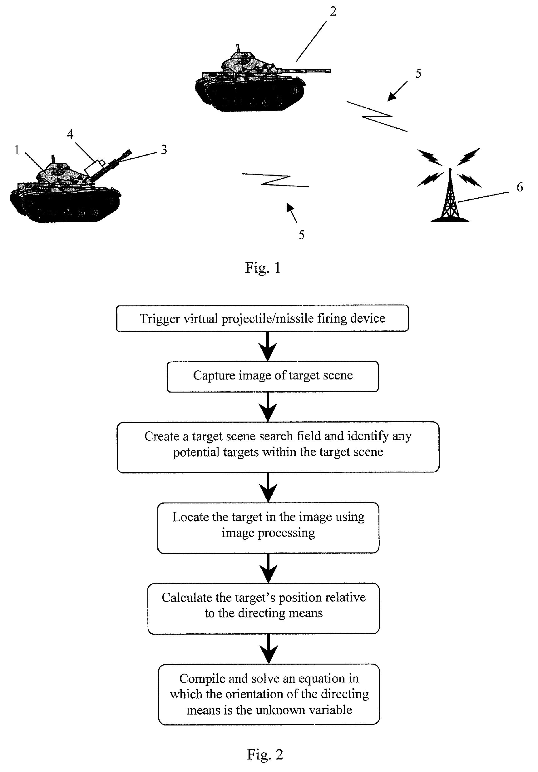
[0009] When a virtual projectile / missile is fired, the simulation system is provided with information concerning how the directing means is oriented from the captured target scene image and with information concerning the geographical position of potential targets in the line of fire of the virtual projectile / missile at the time of firing said virtual projectile / missile. The accurate orientation of the directing means of the virtual projectile / missile firing device can therefore be accurately determined using this information. Accurate determination of the orientation of the directing means allows a more accurate ballistic trajectory of the virtual projectile / missile to be determined and this consequently enhances the realism and improves the effectiveness of the simulation exercise.

Problems solved by technology

A disadvantage of such a simulation system is that a lot of equipment has to be mounted on the vehicles that participate in a simulation exercise, which makes installation of the system complex and time consuming.
The amount of hardware that is necessary also increases the cost of such a system.
Another disadvantage is that optical equipment on the shooter tank may be damaged by optical radiation reflected from optical equipment, such as prisms, mounted on the target tank, especially if the target tank comes too close to the shooter tank.
The laser scanner transmitter can consequently not be used tactically without limitation.
Furthermore, the gunning of targets outside the field of view of the laser scanner transmitter is not possible.
Several conventional simulation systems use a compass to determine the orientation of a gun barrel however the accuracy of compasses is very low and metal objects and electrical sources, such as power lines, guns, trucks, tanks, telephone wires, barbed wire or steel helmets can affect their performance and consequently their reliability.
If the orientation of the gun barrel is inaccurate, the calculation of the ballistic trajectory of the virtual projectile / missile fired from the gun barrel will be inaccurate.
An inaccurate and therefore unrealistic simulation system will prevent participants in a simulation exercise from developing their aiming and shooting ability.

Method used


Image

  • Simulation system, method and computer program
  • Simulation system, method and computer program

Examples


Embodiment Construction

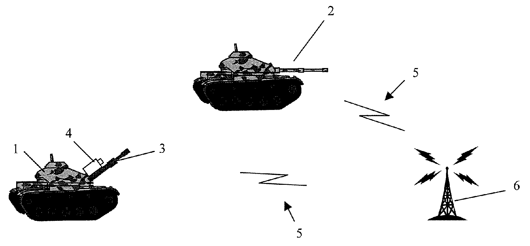
[0031]FIG. 1 shows a simulation system used to simulate the firing of virtual anti-tank projectiles / missiles from tank 1 at tank 2 during a simulation exercise. Tank 1 comprises a gun barrel 3 that is movable by means of the revolvable turret on which it is mounted and which is arranged to direct a virtual anti-tank projectile / missile towards the target tank 2.

[0032] The tanks 1 and 2 are equipped with sensors, such as GPS-sensors, turret traversing sensors, a compass to give a rough indication of the compass bearing of the gun barrel, a gyroscope and gun barrel orientation sensors that provide information concerning the elevation and rotation of the gun barrel towards the vertical plane. Additional sensors, such as a wind sensor may also be utilized if such information is to be considered in calculating the ballistic trajectory of the virtual anti-tank projectile / missile.

[0033] Time-logged information 5 concerning the position and orientation of the tanks 1, 2 and parts thereof i...


PUM


Abstract

Simulation system comprising at least one virtual projectile / missile firing device (1) having movable directing means (3) to direct a virtual projectile / missile towards a target (2) and means to determine the position of said at least one virtual projectile / missile firing device and the target whereby the simulation system comprises means (4) to capture at least one image of the target scene in front of the directing means (3) and means to process the, or each, image so as to determine the orientation of the directing means (3).

Description

FIELD OF THE INVENTION [0001] The present invention relates to a simulation system and, more particularly, to a system comprising at least one virtual projectile / missile firing device having movable directing means to direct a virtual projectile / missile (i.e. a self-propelling weapon, such as a rocket, or a non-self-propelling weapon that is thrown or projected) towards a target and a method for determining the orientation of the directing means of a virtual projectile / missile firing device. BACKGROUND OF THE INVENTION [0002] Weapon simulators are widely used to take the place of actual weapons during simulation exercises. [0003] U.S. Pat. No. 6,386,879 describes a gunnery simulation system in which a turret-mounted gun on a shooter tank with a laser scanner transmitter in its barrel emits a laser beam upon a trigger pull. The laser beam is directed towards a target tank based upon a shooter's ranging and tracking using a standard fire computer. The target tank is scanned with the l...

Claims


Application Information

Patent Timeline
IPC IPC(8): F41A33/00
CPCF41G3/2644F41G3/2611
Inventor TENGBLAD, ADAM
Owner SAAB AB
Learn More