Inflow control device with passive shut-off feature

a control device and inflow technology, applied in survey, borehole/well accessories, construction, etc., can solve the problems of reducing the profit of production, accelerating the inclination of the opening, and nearby gas being drawn down or drawn up into the production tubing at a faster rate, so as to reduce the gas flow

Inactive Publication Date: 2006-04-13
BAKER HUGHES INC
View PDF14 Cites 137 Cited by
  • Summary
  • Abstract
  • Description
  • Claims
  • Application Information

AI Technical Summary

Benefits of technology

[0010] In aspects the present invention provides systems, devices and methods for controlling the flow of fluid from a subterranean formation into a production tubular. Flow of these formation fluids can be controlled with respect to one or more selected parameter relating to the wellbore fluid, such as the type of fluid, the phase of fluid, fluid pressure, fluid velocity, water content, etc. In one embodiment, a flow control device for controlling fluid flow into the production tubular uses a flow restriction member that moves between an full flow position (or open position) and a restricted flow position (or closed position) when actuated by a phase change of the formation fluid. For example, the flow restriction member can be sensitive to a change in density of the formation fluid. In one arrangement, the flow restriction member is formed of a material having a density that is lower than a density of a sel

Problems solved by technology

During later stages of production of hydrocarbons from a subterranean production zone, water and/or gas often enters the production fluid, making production less profitable as the production fluid becomes increasingly diluted.
A particular problem arises in horizontal wellbore sections that pass through a single layer containing production fluid.
If fluid enters the production tubing unevenly, it may draw down the production layer non-uniformly, causing nearby gas to be drawn down, or water drawn up, into the productio

Method used


Image

  • Inflow control device with passive shut-off feature
  • Inflow control device with passive shut-off feature
  • Inflow control device with passive shut-off feature

Examples


Embodiment Construction

[0025] The present invention relates to devices and methods for controlling production of a hydrocarbon producing well. The present invention is susceptible to embodiments of different forms. There are shown in the drawings, and herein will be described in detail, specific embodiments of the present invention with the understanding that the present disclosure is to be considered an exemplification of the principles of the invention, and is not intended to limit the invention to that illustrated and described herein.

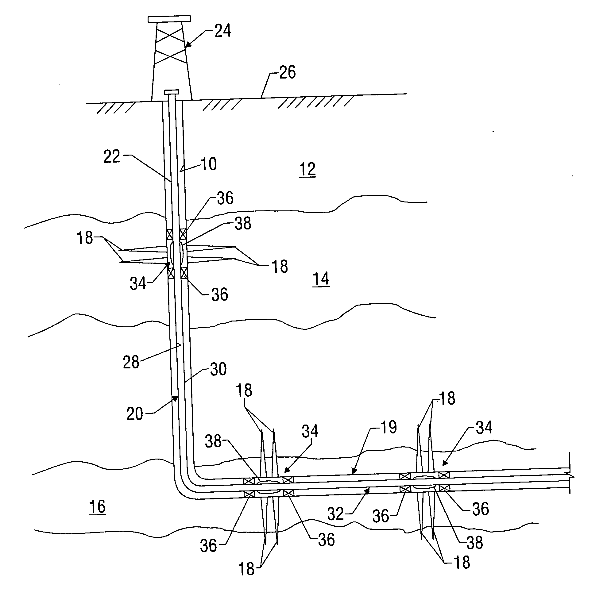
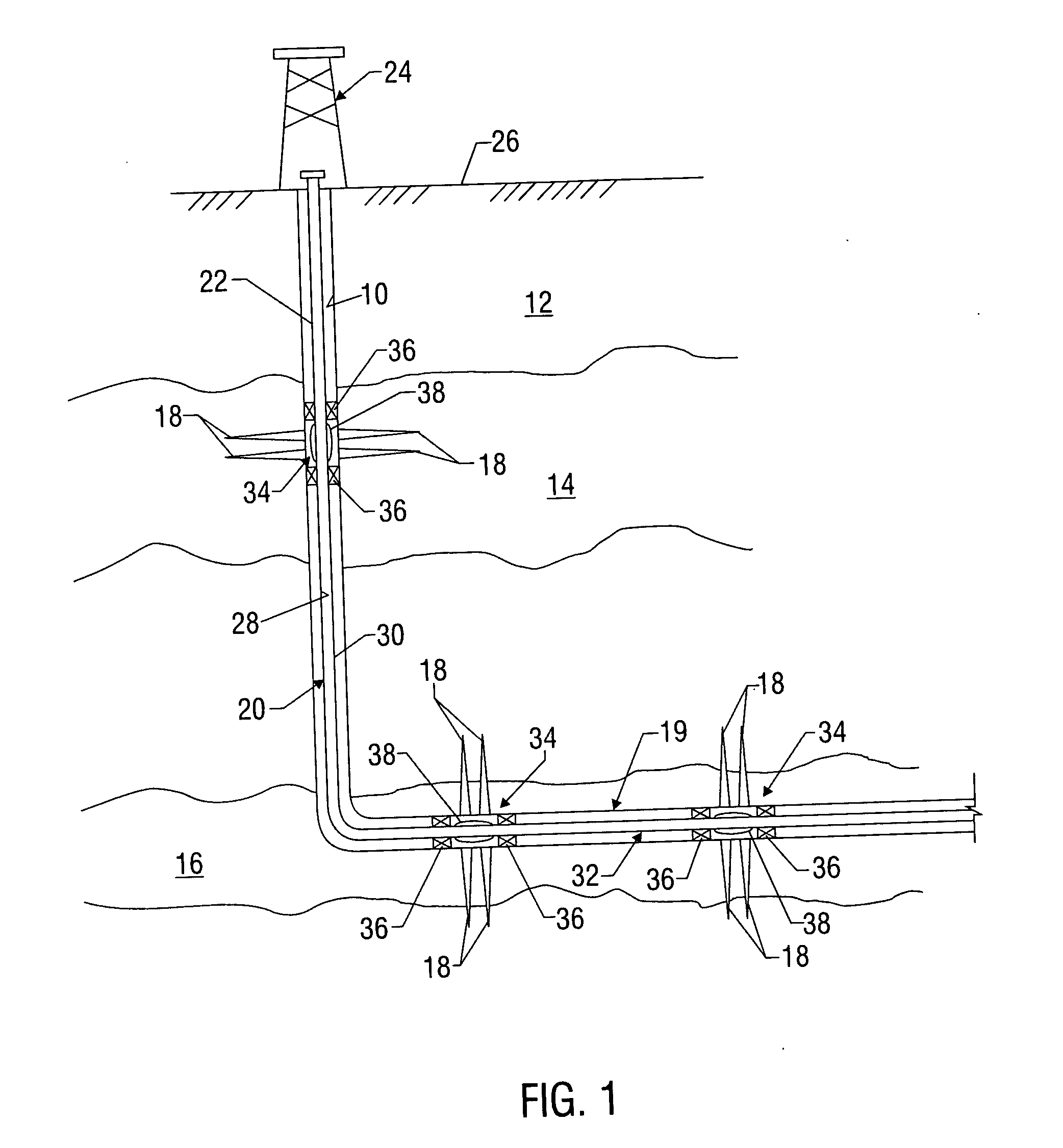
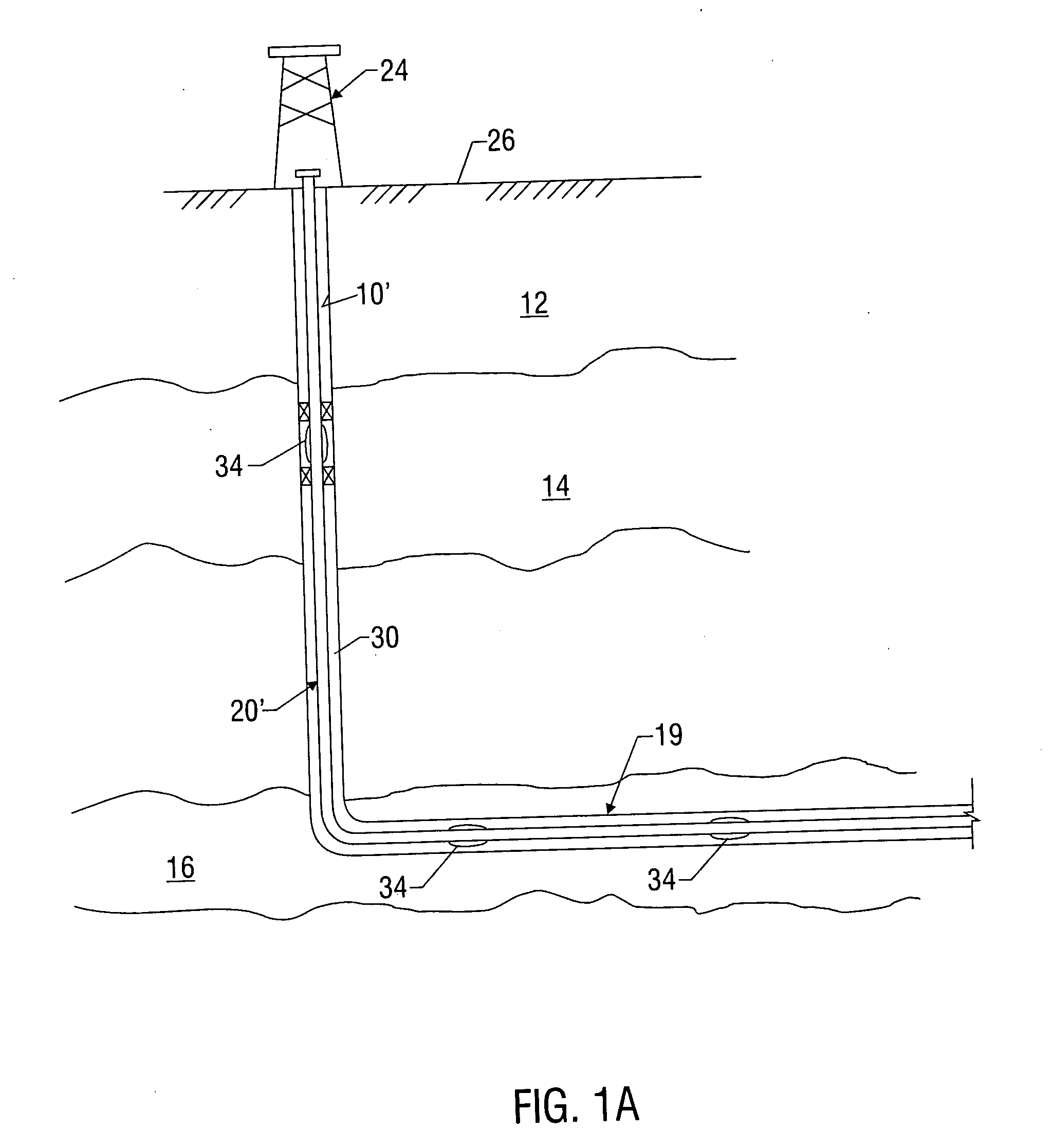
[0026] Referring initially to FIG. 1, there is shown an exemplary wellbore 10 that has been drilled through the earth 12 and into a pair of formations 14, 16 from which it is desired to produce hydrocarbons. The wellbore 10 is cased by metal casing, as is known in the art, and a number of perforations 18 penetrate and extend into the formations 14,16 so that production fluids may flow from the formations 14, 16 into the wellbore 10. The wellbore 10 has a deviated, or sub...


PUM


Abstract

Devices and methods for control flow of formation fluids respect to one or more selected parameter relating to the wellbore fluid. In one embodiment, a flow control device for controlling fluid flow into the production tubular uses a flow restriction member that is actuated by a character change of the formation fluid, such as liquid to gas or oil to water. The flow restriction member can be sensitive to a change in density of the formation fluid. The flow restriction member is passive, self-regulating and does not need any power source or control signal to control fluid flow. In one embodiment, the flow control device automatically rotates into a predetermined orientation upon being positioned in the wellbore. A seal disposed on the flow control devices expands into sealing engagement with an enclosure after the flow control device assumed the desired predetermined position.

Description

CROSS-REFERENCE TO RELATED APPLICATIONS [0001] This application is a continuation in part of U.S. patent application Ser. No. 11 / 193,182 filed on Jul. 29, 2005, titled “DOWNHOLE INFLOW CONTROL DEVICE WITH SHUT-OFF FEATURE” which takes priority from U.S. Provisional Application Ser. No. 60 / 592,496 filed on Jul. 30, 2004.BACKGROUND OF THE INVENTION [0002] 1. Field of the Invention [0003] The invention relates generally to systems and methods for selective control of fluid flow into a production string in a wellbore. In particular aspects, the invention relates to devices and methods for actuating flow control valves in response to increased water or gas content in the production fluids obtained from particular production zones within a wellbore. In other aspects, the invention relates to systems and methods for monitoring flow rate or flow density at completion points and adjusting the flow rate at individual production points in response thereto. [0004] 2. Description of the Related ...

Claims


Application Information

Patent Timeline
IPC IPC(8): E21B43/12
CPCE21B34/08E21B34/10E21B43/12E21B43/14E21B43/32E21B2034/005E21B2200/05
Inventor CORONADO, MARTINCROW, STEVEHENRIKSEN, KNUT H.
Owner BAKER HUGHES INC
Why Eureka
Try Eureka