Floating-caliper disk brake

a disc brake and floating caliper technology, applied in the direction of axially engaging brakes, brake types, braking elements, etc., can solve the problems of high displacement force of floating calipers in relation to the brake holder, difficult to exact spring rating, and large variations of spring tension force, so as to ensure the ease of displacement of floating calipers, prevent undesirable rattling and radial lifting of floating calipers or brake pads out of the brake holder, and reduce elastic deformation

Inactive Publication Date: 2006-04-13
CONTINENTAL TEVES AG & CO OHG
View PDF4 Cites 14 Cited by
  • Summary
  • Abstract
  • Description
  • Claims
  • Application Information

AI Technical Summary

Benefits of technology

[0004] In view of the above, an object of the invention is to provide a floating-caliper disc brake with a brake holder firmly attached to the vehicle and a displaceable floating caliper, which ensures a functionally safe and comfortable displaceable mounting support of the floating caliper on the brake holder for different caliper designs.
[0005] This object is achieved by a floating-caliper disc brake for motor vehicles comprises a brake holder firmly attached to the vehicle, on which a floating caliper is axially displaceably mounted. In particular, one or more pin guides may be arranged in this respect between the brake holder and the floating caliper. A locking element is provided for the radial fixation of the floating caliper on the brake holder, being detachably secured to the floating caliper and being arranged with at least one portion on the brake holder in an axially displaceable manner. The locking element is secured to the floating caliper so as to be adjustable in its radial position. This allows the accurate adjustment of the radial clearance between brake holder and floating caliper in conformity with the respective case of application and irrespective of any manufacturing tolerances developing. On the one hand, this arrangement ensures ease of displacement of the floating caliper in relation to the brake holder, while undesirable rattling and radial lifting of the floating caliper or of the brake pads out of the brake holder is prevented, on the other hand. The locking element active in a radial direction is designed in particular as a generally stiff component, e.g. as a sheet-metal component, in order to reduce elastic deformations and, hence, permit only a minimum scope of radial motion for the floating caliper. As a result, the development of undesirable rattling noises in defined operating conditions of the brake is reliably prevented.
[0006] For the radially adjustable attachment of the locking element at the floating caliper, a favorable aspect of the floating-caliper disc brake provides that the locking element is attached to an associated pin at the floating caliper through a radially extending elongated hole or any other appropriately sized opening, such as a U-shaped opening, a slot, a large bore, etc. The elongated hole or the opening provides an accommodation with a play for the associated pin so that a radial setting range is achieved when attaching the locking element. This allows purposefully adjusting the radial clearance between brake holder, brake pad, and floating caliper by means of the subsequent mounting of the locking element on the floating caliper. Radial displacement of the locking element permits adjusting the desired radial clearance and subsequently securing the locking element to the floating caliper. The actual attachment of the locking element to the floating caliper is carried out by means of a pin, which may preferably be configured as a screw or any other appropriate fastening bolt and is attached in an associated bore in the floating caliper. The locking element is clamped in between the floating caliper and the pin and fixed by means of this clamping effect in its radial position at the floating caliper.
[0007] According to an alternative variant of the floating-caliper disc brake, the locking element is detachably fastened to a carrier connected firmly to the floating caliper. This reduces the machining effort at the floating caliper because a fastening bore at the floating caliper for the locking element is omitted. The carrier especially has a disc-shaped design and is firmly connected to the floating caliper inside an associated opening therein, for example, by means of a press fit. The locking element can then be fastened to the carrier in a detachable manner by way of a fastening bolt, as described hereinabove.
[0008] A favorable aspect of the floating-caliper disc brake is achieved in that the portion of the locking element that is axially displaceably arranged on the brake holder has a radially elastic design. This way, it is not only possible to purposefully adjust the radial clearance between the floating caliper and the brake holder. Rather, a defined adjustment of elastic preload in a radial direction between floating caliper and brake holder is also rendered possible.
[0009] Another suitable design of the floating-caliper disc brake is achieved in that an elastic spring arm is provided at the locking element, which bears against the brake holder with a preload in circumferential direction and in an axially displaceable manner. This arrangement will clamp the floating caliper elastically in a circumferential direction in relation to the brake holder that is fixed to the vehicle. This condition proves favorable above all in defined installation positions of the floating-caliper disc brake on the vehicle wheel in terms of preventing rattling noises. The elastic spring arm is either formed integrally with the locking element or connected thereto in an appropriate fashion. The direct coupling of the elastic spring arm to the locking element favorably reduces the expenditure in components for the floating-caliper disc brake.

Problems solved by technology

However, this necessitates very great tension forces of the housing holding spring, above all in floating calipers with a high weight, what unfavorably causes a high amount of displacement forces of the floating caliper in relation to the brake holder.
Thus, the manufacturing tolerances will render the exact spring rating very difficult so that great variations of the spring tension force will frequently occur in practical operations.
However, the manufacturing tolerances of the individual components that must be taken into consideration cause an undesirably great radial clearance between brake holder, brake pad, and floating caliper so that rattling noises can develop.

Method used


Image

  • Floating-caliper disk brake
  • Floating-caliper disk brake
  • Floating-caliper disk brake

Examples


Embodiment Construction

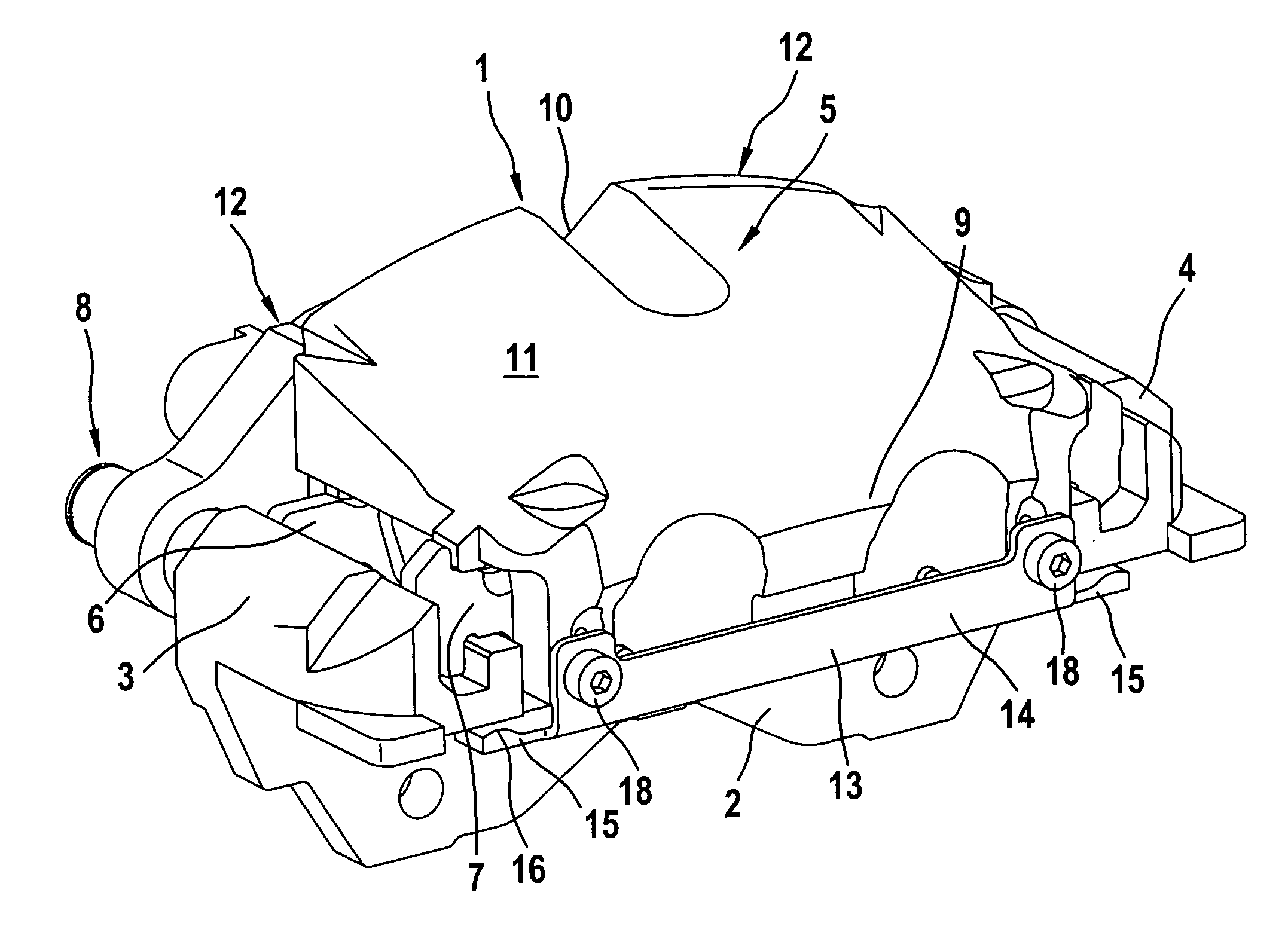
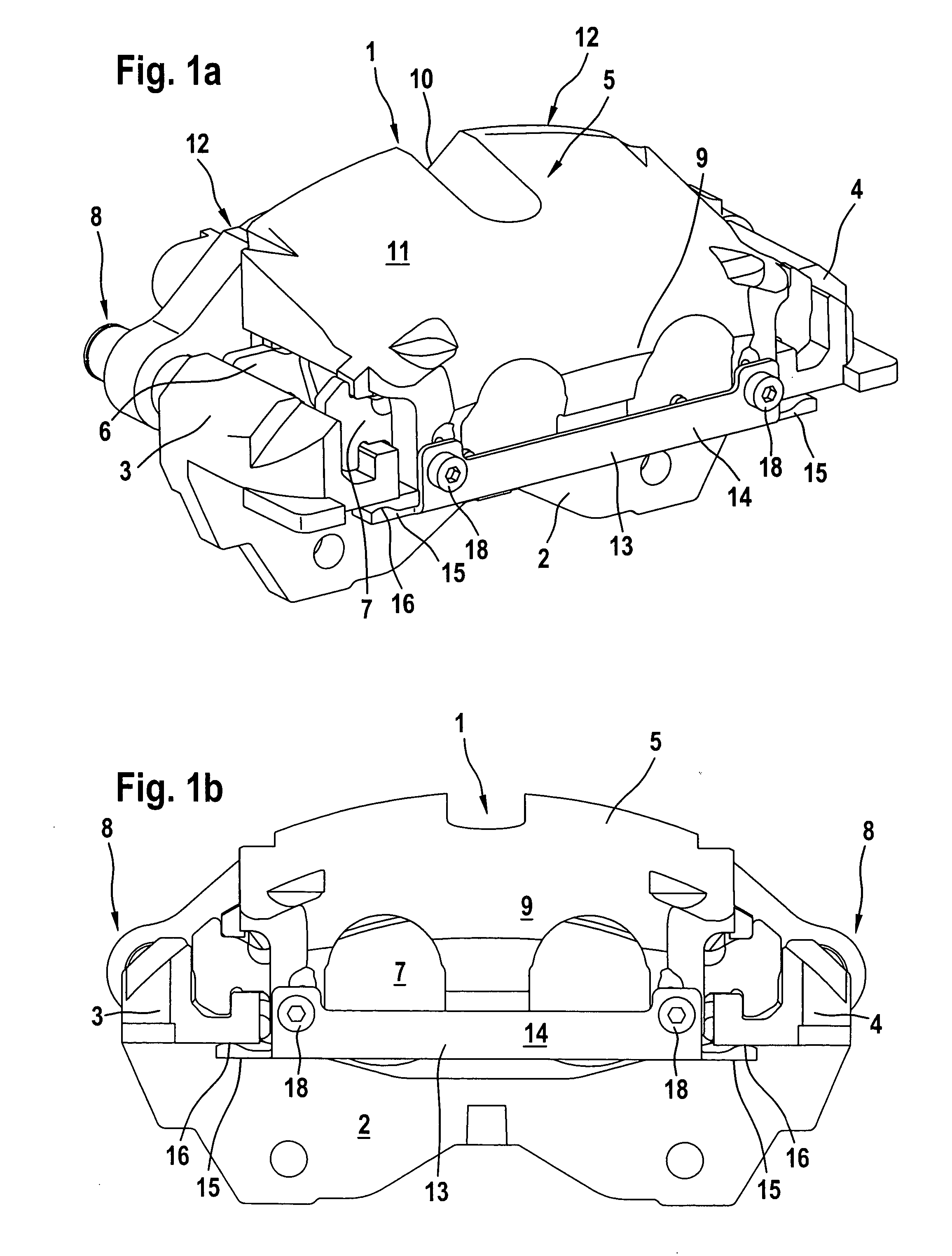
[0018] The floating-caliper disc brake 1 for a motor vehicle shown in FIGS. 1 to 5 comprises a brake holder 2 arranged firmly on the vehicle and being either integrated directly into a component on the vehicle, e.g. a steering knuckle, or mounted on a component of this type. Only those structural shapes of the brake holder 2 can be taken from the Figures, which can be mounted on the vehicle. With two axially extending holder arms 3, 4 the brake holder 2 straddles the edge of an associated brake disc, which is not shown for the sake of clarity in all the Figures. In the holder arms 3, 4, brake pads 6, 7 arranged on either side of the brake disc with respect to the brake disc axis are axially displaceably guided and supported in a circumferential direction, with said brake pads 6, 7 respectively abutting radially in the holder arms 3, 4. A brake caliper 5 that is axially displaceably mounted on the brake holder 2 straddles the brake pads 6, 7 along with the brake disc. To this end, pr...


PUM


Abstract

The invention relates to a floating-caliper disc brake of a motor vehicle including a brake holder firmly attached to the vehicle and a floating caliper that is mounted on the brake holder so as to be axially displaceable. In this arrangement, the floating caliper is displaceably mounted on the brake holder, preferably by means of at least one pin guide. A radial fixation of the floating caliper on the brake holder is carried out by a locking element that is detachably secured to the floating caliper and with a portion is axially displaceably arranged on the brake holder. To improve ease of displacement of the floating caliper and to prevent undesirable radial movements of the floating caliper, the locking element is secured to the floating caliper so as to be adjustable in its radial position. As a result, it is possible to adjust a defined radial clearance between the floating caliper and the brake holder.

Description

TECHNICAL FIELD [0001] The present invention relates to a floating-caliper disc brake of a motor vehicle including a brake holder firmly attached to the vehicle and a floating caliper that is mounted on the brake holder such as to be axially displaceable. In this arrangement, the floating caliper is displaceably mounted on the brake holder frequently by means of at least one pin guide. BACKGROUND OF THE INVENTION [0002] Thus, DE 40 24 484 C2 discloses a floating-caliper disc brake of this type including a brake holder and a floating caliper wherein the floating caliper is axially displaceably mounted on the brake holder by means of pin guides. Further, the associated brake pads are axially displaceably guided on the brake holder and supported in a circumferential direction. The displaceable floating caliper is elastically clamped in relation to the brake holder in a radial direction with respect to the brake disc axis by means of a housing holding spring. To this end, the housing ho...

Claims


Application Information

Patent Timeline
Patent Type & Authority Applications(United States)
IPC IPC(8): F16D65/14F16D55/227
CPCF16D55/227F16D2055/0041
Inventor THIEL, RUDOLF
Owner CONTINENTAL TEVES AG & CO OHG
Why Eureka
Try Eureka