Raindrop detection apparatus

a detection apparatus and raindrop technology, applied in the direction of vehicle maintenance, vehicle cleaning, instruments, etc., can solve the problems of increased manufacturing cost, waste of inability to use light emitted to the gap (not received by the light receiving unit), so as to reduce the manufacturing cost of the raindrop detection apparatus

Active Publication Date: 2006-04-13
DENSO CORP
View PDF9 Cites 21 Cited by
  • Summary
  • Abstract
  • Description
  • Claims
  • Application Information

AI Technical Summary

Benefits of technology

[0012] Generally, the raindrop detection apparatus is mounted at a position exposed to sunshine, so that the lens units may be deformed due to heat. According to the present invention, even when the first lens unit and the second lens unit are thermally deformed, a major part of the rejected light can be converged at the light receiving unit. Because polycarbonate and the like are cheap, the manufacture cost of the raindrop detection apparatus can be reduced.
[0013] More preferably, the first lens unit is divided into two parts by a first virtual plane, which extends along a central axis of the first lens unit and intersects the windshield at a substantially same angle with that between the central axis and the windshield. The two parts are arranged to offset from each other so that distances from the light emitting unit to the two parts become different and a difference between perpendicular heights of the two parts with respect to the windshield becomes small. The second lens unit is divided into two parts by a second virtual plane, which extends along a central axis of the second lens unit and intersects the windshield at a substantially same angle with that between the central axis and the windshield. The two parts are arranged to offset from each other so that distances from the light receiving unit to the two parts become different and a difference between perpendicular heights of the two parts with respect to the windshield becomes small.
[0014] Because the difference between the perpendicular heights of the two parts of the lens unit with respect to the windshield is decreased, the perpendicular overall height of the lens unit with respect to the windshield can be decreased as compared with the case where the lens unit is constructed of the single lens.

Problems solved by technology

Therefore, the manufacturing cost is increased.
The first lens unit has a shape and a construction significantly different from those of the second lens unit (at side of light receiving unit), thus making the optical axis design complex.
Furthermore, in this case, light emitted to the gap is not used (not received by light receiving unit) to be wasted.

Method used


Image

  • Raindrop detection apparatus
  • Raindrop detection apparatus
  • Raindrop detection apparatus

Examples


first embodiment

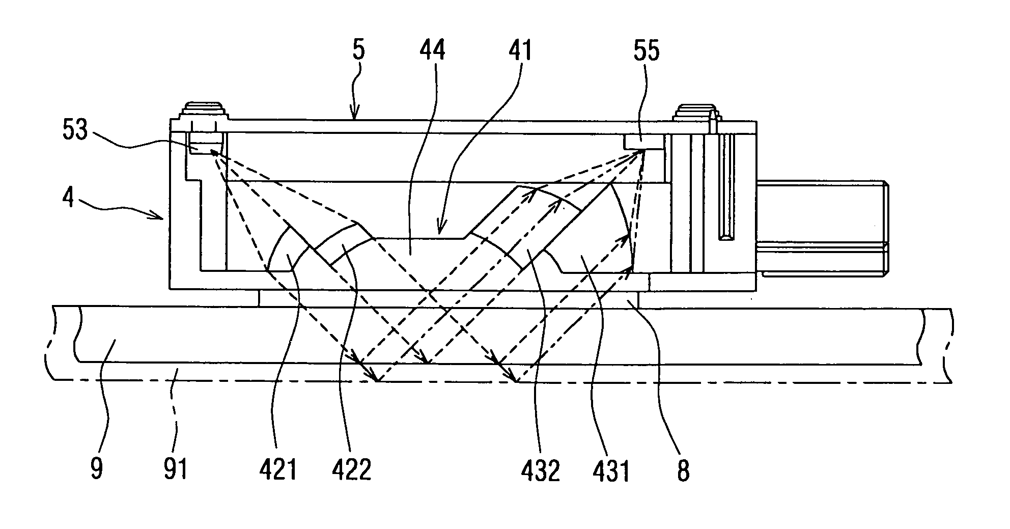
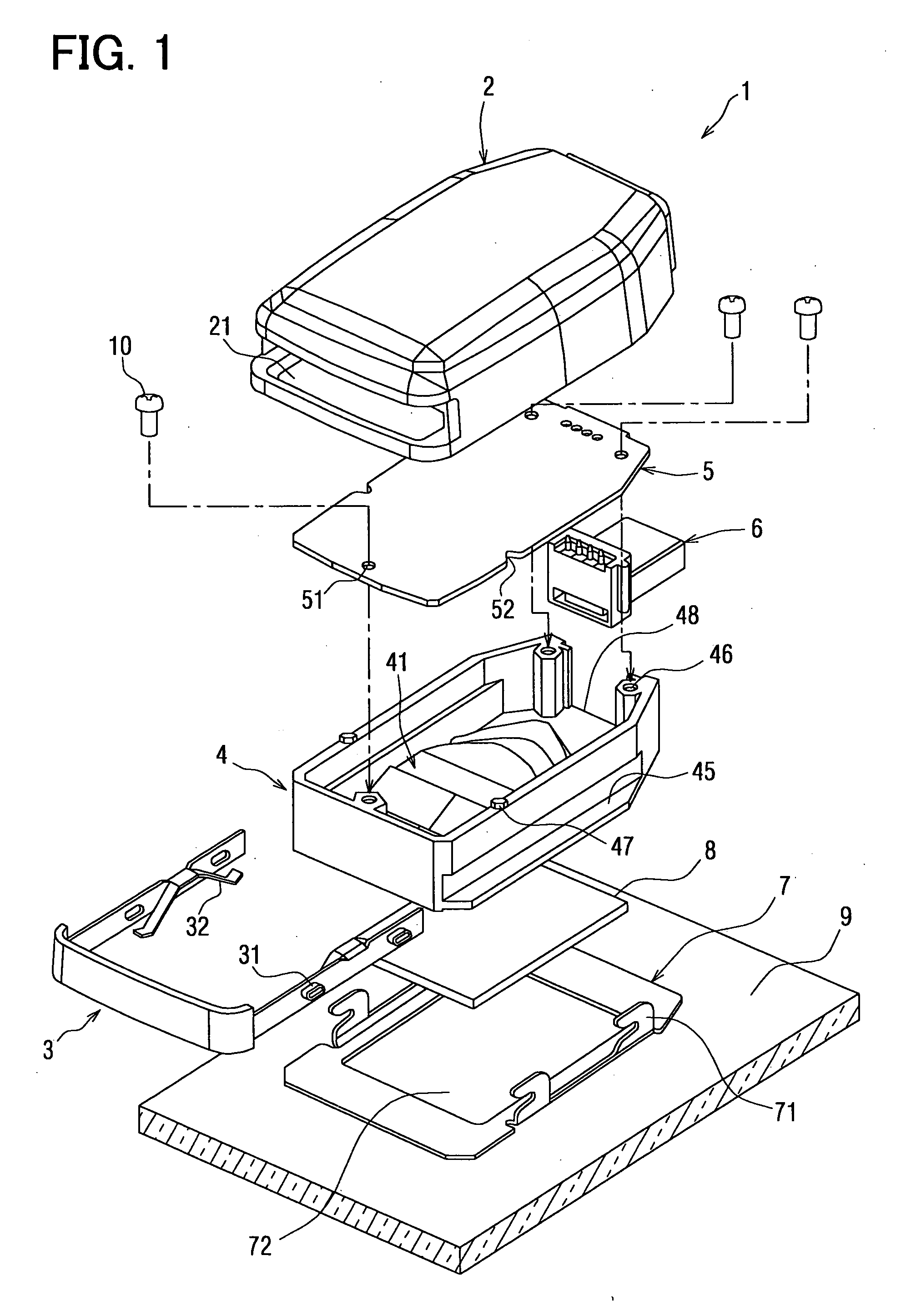
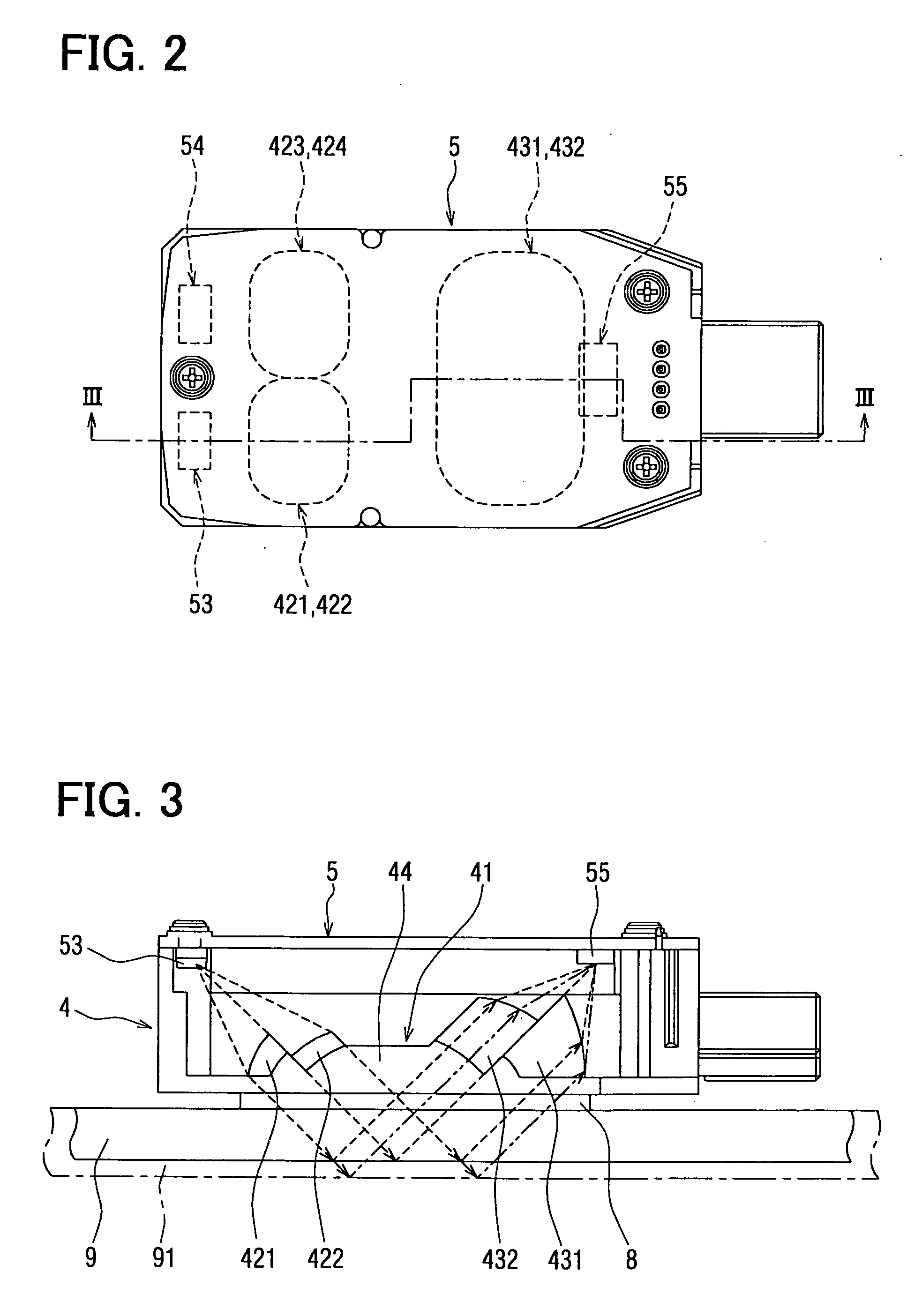
[0022] A raindrop detection apparatus 1 according to a first embodiment of the present invention is suitably used to detect an amount of raindrop landed on an outer surface of a window glass 9 (e.g., windshield) of a vehicle, for example. The raindrop detection apparatus 1 is attached to an inner surface of the windshield 9 without obstructing the sight (field of view) of a driver. Referring to FIG. 1, the raindrop detection apparatus 1 is provided with a cover 2, a case unit 4, a prism 41, a circuit board 5, a connector 6, a stopper 3, a silicon sheet 8, a bracket 7 and the like. The case unit 4 is integrated with the prism 41.

[0023] The bracket 7 is beforehand fixed (for example, by bonding) to the windshield 9 at the position where the raindrop detection apparatus 1 is to be mounted. As shown in FIG. 1, the bracket 7 has multiple (e.g., four) engagement hook portions 71 which are evenly arranged at two opposite sides of the bracket 7. The bracket 7 has an opening 72 at a substan...

second embodiment

[0070] A second embodiment of the present invention is described with reference to FIG. 6. The second embodiment is a modification of the above-described first embodiment.

[0071] Referring to FIG. 6, two recess portions 49 for accommodating a spring 321 are respectively formed at two opposite sides of the fence wall of the case unit 4. The spring 321 can be constructed of, for example, a steel sheet and bent to have a shape shown in FIG. 6. The spring 321 pushes the prism 41 toward the windshield 9 at a substantially central portion of the prism 41. In this embodiment, the single spring 321 is used instead of the two springs 32, which are provided for the stopper 3 as described in the first embodiment.

[0072] According to the second embodiment, two longitudinal-direction ends of the spring 321 are positioned at the outer side of the case unit 4 when being attached to the prism 41. Thus, when the raindrop detection apparatus 1 is mounted at the windshield 9, the two ends of the sprin...


PUM


Abstract

A raindrop detection apparatus includes a light emitting unit for emitting light to an inner side of a windshield, a light receiving unit for receiving the light reflected by an outer surface of the windshield, a first lens unit which is arranged between the windshield and the light emitting unit to convert the light from the light emitting unit into parallel light, and a second lens unit which is arranged between the windshield and the light receiving unit to converge the reflected light at the light receiving unit. The second lens unit is larger than a radial cross section of the reflected light. An amount of raindrop landed on the outer surface of the windshield is detected based on an intensity of the light received by the light receiving unit.

Description

CROSS REFERENCE TO RELATED APPLICATION [0001] This application is based on a Japanese Patent Application No. 2004-282269 filed on Sep. 28, 2004, the disclosure of which is incorporated herein by reference. FIELD OF THE INVENTION [0002] The present invention relates to a raindrop detection apparatus. The raindrop detection apparatus is suitably used in a wiper control device for a vehicle, for example. BACKGROUND OF THE INVENTION [0003] Generally, a raindrop detection apparatus is provided in a wiper control device for a vehicle to detect raindrop landed on a windshield of the vehicle, for example, referring to JP-A-2001-521158 (U.S. Pat. No. 5,898,183) and JP-A-2001-66246 (U.S. Pat. No. 6,507,015). [0004] The raindrop detection apparatus has a first lens unit that converts light from a light emitting unit into parallel light, a light conducting unit that conducts the parallel light to the windshield and conducts light reflected by an outer surface of the windshield, and a second len...

Claims


Application Information

Patent Timeline
Patent Type & Authority Applications(United States)
IPC IPC(8): G02B6/42
CPCB60S1/0822B60S1/0833B60S1/0888
Inventor ISHIKAWA, JUNICHI
Owner DENSO CORP
Why Eureka
Try Eureka