Motor vibration damping device

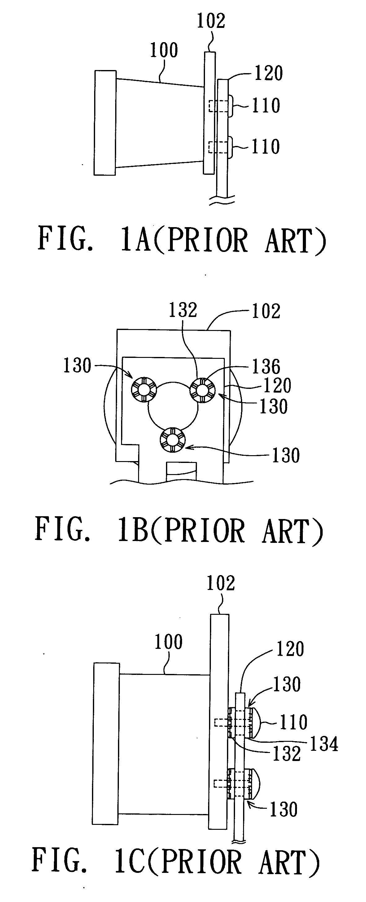
a technology of vibration damping and damping device, which is applied in the direction of shock absorbers, machine supports, transportation and packaging, etc., can solve the problems of high-frequency noise generation, inability to effectively prevent resonance high-frequency noise and the start high-frequency noise generated between the holding piece b>102/b> and the mechanic fixing piece b>120/b>, and achieve the effect of preventing high-frequency noise and reducing manufacturing costs

Inactive Publication Date: 2006-04-13
BENQ CORP
View PDF4 Cites 8 Cited by
  • Summary
  • Abstract
  • Description
  • Claims
  • Application Information

AI Technical Summary

Benefits of technology

[0008] It is therefore an object of the invention to provide a motor vibration damping device. By using a connecting part to combine a number of dampers into a single piece, not only motor vibration energy transmitted to the mechanic fixing piece can be reduced to prevent high-frequency noise generated by the motor, but also the fabrication time and the manufacturing cost can be lowered.

Problems solved by technology

Especially when two different kinds of metals are fixed together, the frequency resonance effect will be enhanced, and thereby it generates high-frequency noise.
However, fabricating these dampers 130 onto the mechanic fixing piece 120 usually takes a long time.
Therefore, the resonance high-frequency noise and the start high-frequency noise generated between the holding piece 102 and the mechanic fixing piece 120 cannot be effectively prevented.

Method used


Image

  • Motor vibration damping device
  • Motor vibration damping device
  • Motor vibration damping device

Examples


embodiment one

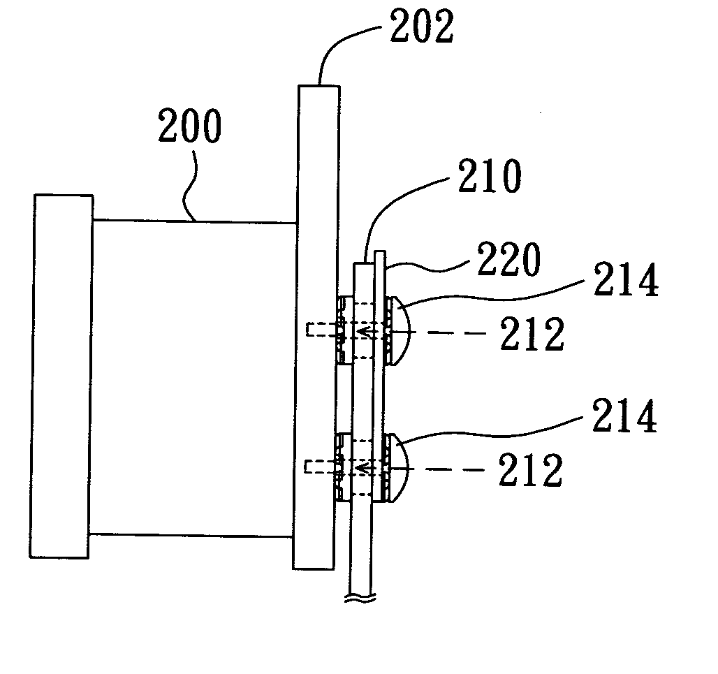
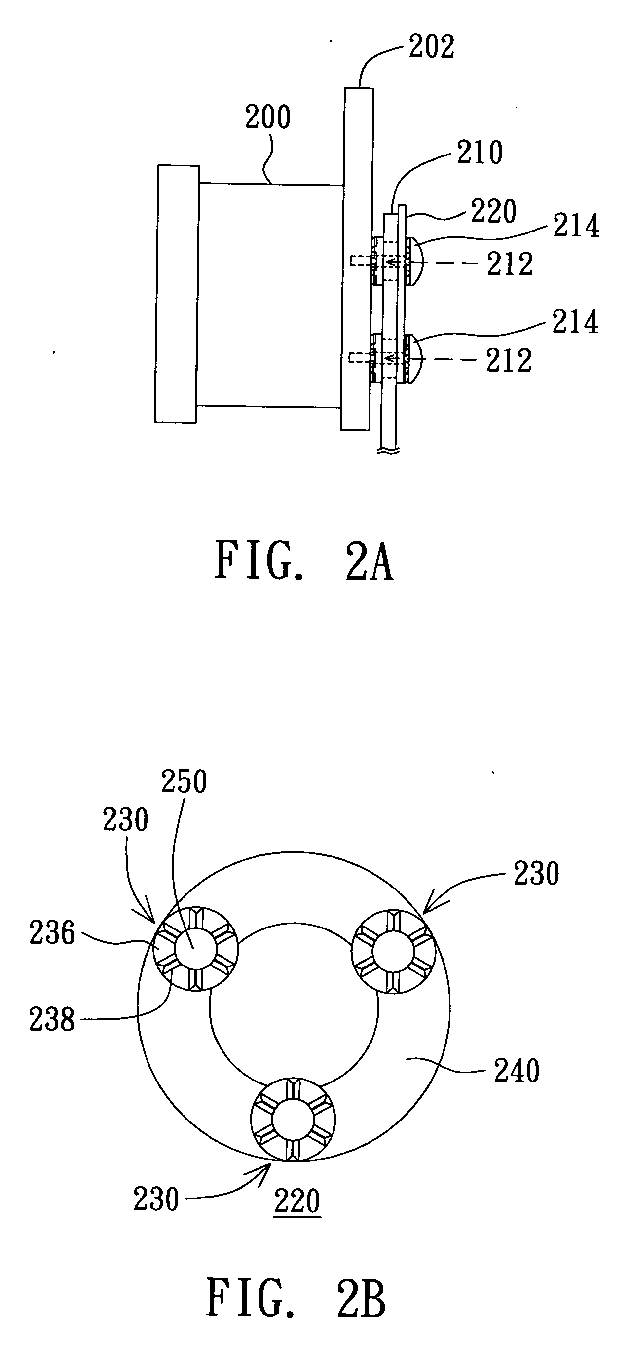
[0024] Referring to FIG. 2A, a lateral view of fixing the motor on the mechanic fixing piece configured with a motor vibration damping device according to the first embodiment of the invention is shown. The motor 200, such as the color wheel motor in a projector, usually has a holding piece 202 for fixing the motor 200 on the mechanic fixing piece 210. The mechanic fixing piece 210 has three fixing holes 212, configured by an equal distance from one another in two-dimension plane, for combining with the screws 214 to fix the holding piece 202 on the mechanic fixing piece 210. Only two fixing holes 212 are shown in FIG. 2A to avoid figure complication. The motor vibration damping device 220 is disposed on the mechanic fixing piece 210 for reducing motor vibration energy transmitted through the holding piece 202 directly or further through the screws 214 to the mechanic fixing piece 210.

[0025] Referring to FIG. 2B and FIG. 2C at the same time, a vertical view and a lateral view of th...

embodiment two

[0028] Referring to FIG. 3A, a lateral view of motor fixing structure using the motor vibration damping device according to the second embodiment of the invention is shown. The motor 300, such as the color wheel motor in a projector, includes a holding piece 302 for fixing the motor on the mechanic fixing piece 310. The mechanic fixing piece 310 has three fixing holes 312 configured equally distant from one another in two-dimension plane. Three fixing holes 312 together with three screws 314 are used to fix the holding piece 302 on the mechanic fixing piece 310. The lateral figure FIG. 3A shows only two screw holes 312 in order to prevent complication. The vibration damping device 320 is for reducing vibration energy transmitted to the mechanic fixing piece 310 via the holding piece 302 and the screws 314.

[0029] Referring to FIG. 3B and FIG. 3C, a vertical view and a lateral view of the explored motor vibration damping device 320 in FIG. 3A are shown. The motor vibration damping de...


PUM


Abstract

A motor vibration damping device includes several dampers and a connecting part. Each damper is disposed in a fixing hole of a mechanic fixing piece for reducing motor vibration energy transmitted to the mechanic fixing piece and the connecting part connects the dampers.

Description

[0001] This application claims the benefit of Taiwan application Serial No. 93129492, filed Sep. 29, 2004, the subject matter of which is incorporated herein by reference. BACKGROUND OF THE INVENTION [0002] 1. Field of the Invention [0003] The invention relates in general to a motor vibration damping device, and more particularly to a motor vibration damping device, which can reduce high-frequency noise generated by the motor. [0004] 2. Description of the Related Art [0005]FIG. 1A is a lateral view of the conventional motor disposed on the mechanic fixing piece. Referring to FIG. 1A, the motor 100 includes a holding piece 102, which can be screwed on the mechanic fixing piece 120 by the screws 110. For the holding piece 102 and the mechanic fixing piece 120 are both metal pieces, if there is no medium disposed between the two metal pieces as buffer, motor vibration energy will be easily transmitted to the mechanic fixing piece 120 via the holding piece 102 to generate resonance nois...

Claims


Application Information

Patent Timeline
Patent Type & Authority Applications(United States)
IPC IPC(8): F16F13/00F16F15/08H02K5/24
CPCF16F15/08
Inventor HUANG, HSU-HSINCHIU, I-PINGSHEN, CHUN-MING
Owner BENQ CORP
Why Eureka
Try Eureka