Systems and methods for detection of dielectric change in material and structure

a dielectric change and dielectric technology, applied in the field of detection objects, can solve the problems of dozens of injuries and deaths, incidents causing damage, and affecting the sensitivity of circuitry, so as to avoid being overloaded by a base signal, the effect of improving the sensitivity of the circuitry

Active Publication Date: 2006-04-13
SOUTHWEST RES INST
View PDF10 Cites 11 Cited by
  • Summary
  • Abstract
  • Description
  • Claims
  • Application Information

AI Technical Summary

Benefits of technology

[0015] With regard to other aspects of the disclosure, a method for detecting an object is provided. The method includes steps for measuring a first and second displacement current. The difference between the first and second displacement current is determined by subtracting one of the displacement currents from the other. The difference between the two displacement currents may be nullified

Problems solved by technology

The accidental impingement on concealed objects such as pipes, fibers, and land mines carries an enormous human and/or financial cost.
Further, dozens of injuries and fatalities were reported.
Unfortunately, over half of the incidents causing the damages resulted from outside force i

Method used


Image

  • Systems and methods for detection of dielectric change in material and structure
  • Systems and methods for detection of dielectric change in material and structure
  • Systems and methods for detection of dielectric change in material and structure

Examples


example 1

Detection of Optical Fibers

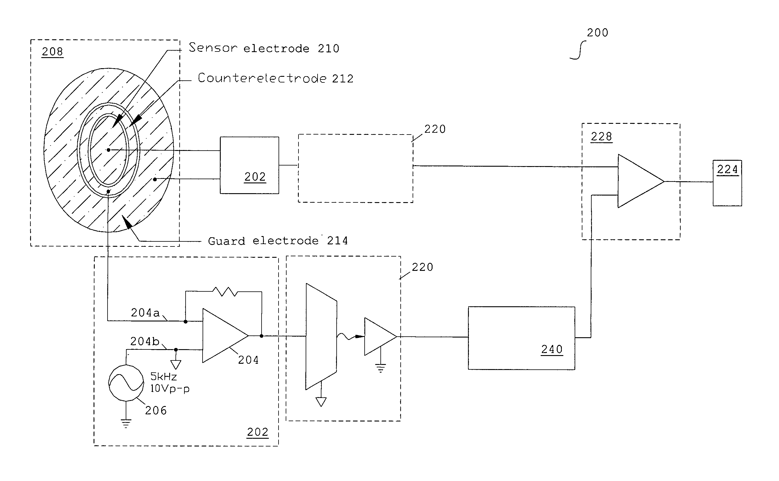
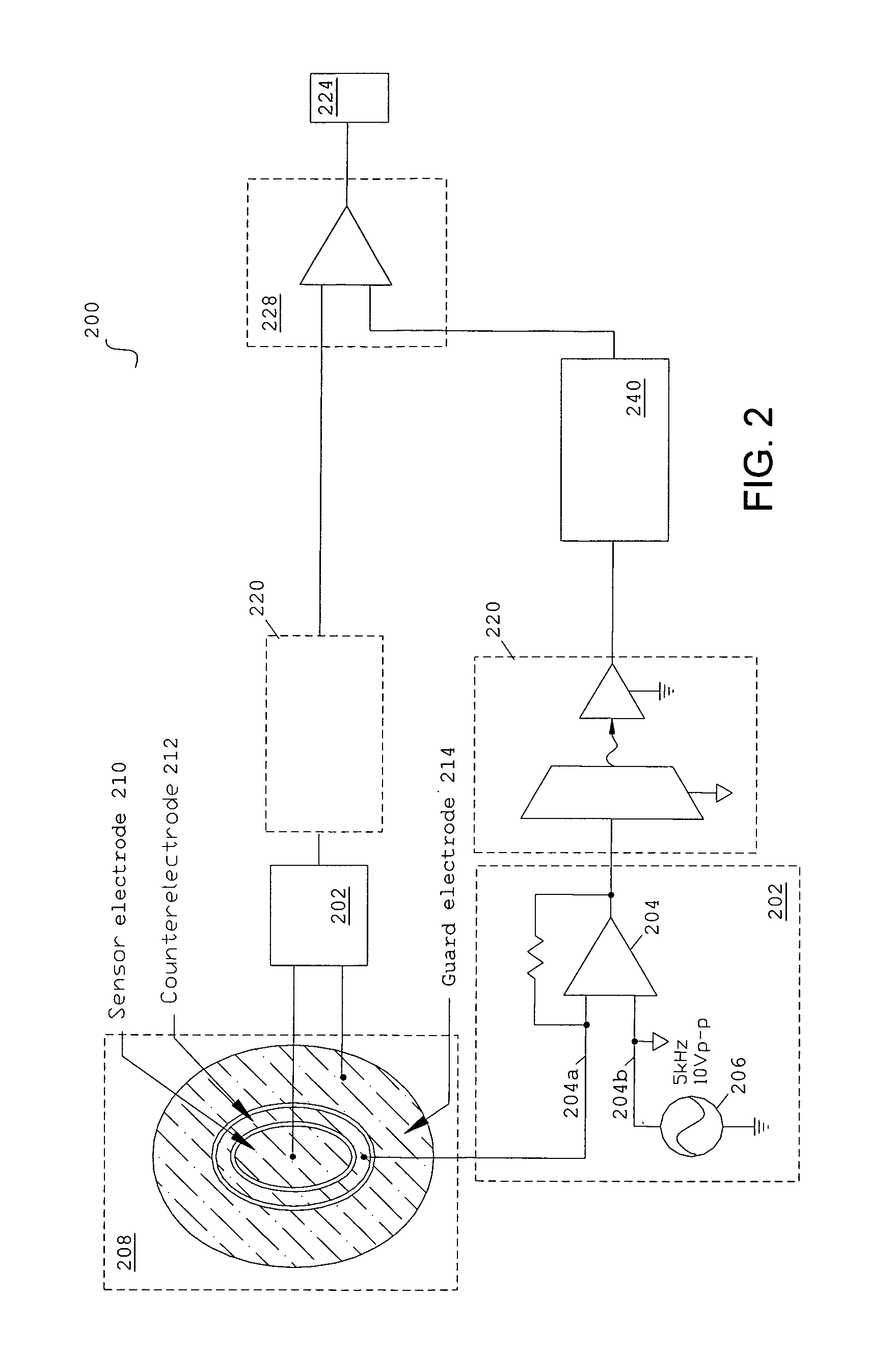
[0050] The phase of the displacement current may contain vital information about the nature of the dielectric material of an object. As illustrated below with reference to FIGS. 5-7, the phase of the signal may also be less sensitive to clutter than the amplitude. Thus, the electronic components of a system, such as system 300, may be selected with high bandwidth to minimize phase errors.

[0051] Three optical fibers, with diameters 0.039″, 0.064″, and 0.028″, respectively, were buried in the surface of a ¼ inch thick gypsum wallboard opposite of the side scanned with the dielectric detector system. The fibers were detected as shown in the image provided in FIG. 5. Because of the detector point spread function, each fiber appears as three bright lines above the dark blue background in the image. The additional, faint linear features at the upper and lower right are most likely the images of seams where the gypsum material was removed temporarily to accommo...


PUM


Abstract

Methods and systems are described for efficiently detecting an object. The system includes at least one electrode for measuring a displacement current. The at least one electrode is coupled to a floating ground configuration provided by an op-amp, where the inverting node of the op-amp is coupled to electrode and the non-inverting node is coupled to a signal generator. The system may include a single capacitance sensor for detecting an object. Systems may include a plurality of capacitance sensors in an array configuration for detecting an object.

Description

[0001] This application claims priority to, and incorporates by reference, U.S. Provisional Patent Application Ser. No. 60 / 602,401 entitled “SYSTEMS AND METHODS FOR DETECTION OF DIELECTRIC CHANGE IN MATERIAL AND STRUCTURE,” which was filed on Aug. 18, 2004.STATEMENT AS TO RIGHTS TO INVENTIONS MADE UNDER FEDERALLY-SPONSORED RESEARCH AND DEVELOPMENT [0002] Aspects of this invention were made with government support by the Maryland Procurement Office, contract No.: MDA904-01-C-2133. Accordingly, the government may have certain rights in this invention.BACKGROUND OF THE INVENTION [0003] 1. Field of the Invention [0004] The present invention relates generally to detecting objects. More particularly, the present invention provides methods and systems for measuring a dielectric change on a surface for assaying and imaging hidden objects. [0005] 2. Description of Related Art [0006] The accidental impingement on concealed objects such as pipes, fibers, and land mines carries an enormous huma...

Claims


Application Information

Patent Timeline
IPC IPC(8): H03K3/00
CPCG01V3/088H03K17/955
Inventor MARTINEZ, ROBERT E.CERWIN, STEPHEN A.GOYEN, TODD H.
Owner SOUTHWEST RES INST
Why Eureka
Try Eureka