Method and device for measuring reflected optical radiation

a technology of optical radiation and optical radiation, applied in the direction of analytical using chemical indicators, laboratory glassware, instruments, etc., can solve the problems of not being able to meet the needs of the prior, and no provision is made to exclude the detection of specular reflectance, etc., to achieve the effect of compactness and low cos

Inactive Publication Date: 2006-04-13
POLYMER TECH SYST
View PDF11 Cites 14 Cited by
  • Summary
  • Abstract
  • Description
  • Claims
  • Application Information

AI Technical Summary

Benefits of technology

[0014] Accordingly, the present invention provides a reflectometer which is sufficiently compact and inexpensive for use in a diagnostic device that is portable and disposable after a single use. The reflectometer also provides for simultaneous analysis of multiple assays within a diagnostic device using precise and accurate measurement of the reaction chemistry of the diagnostic device with results provided in a timely manner for the convenience of the user.

Problems solved by technology

Often, problems arise with initially positioning and subsequently maintaining the proper mounting as the reflectometer is transported and operated.
Furthermore, no provision is made to exclude the detection of specular reflectance which represents a significant noise factor when highly accurate and precise measurements of a selected analyte in a sample is needed.
These needs have not been filled by the prior art.

Method used


Image

  • Method and device for measuring reflected optical radiation
  • Method and device for measuring reflected optical radiation
  • Method and device for measuring reflected optical radiation

Examples


Embodiment Construction

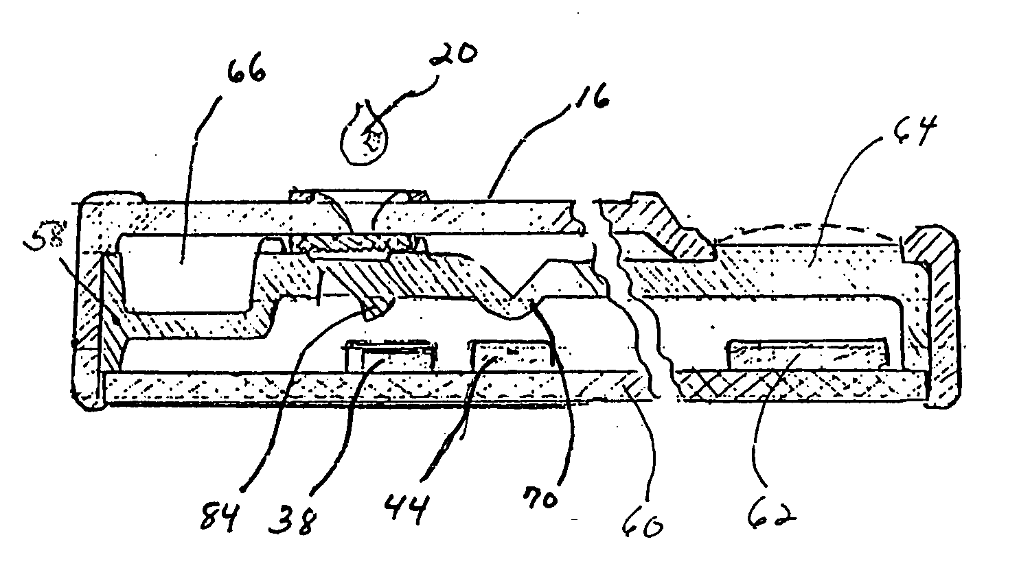
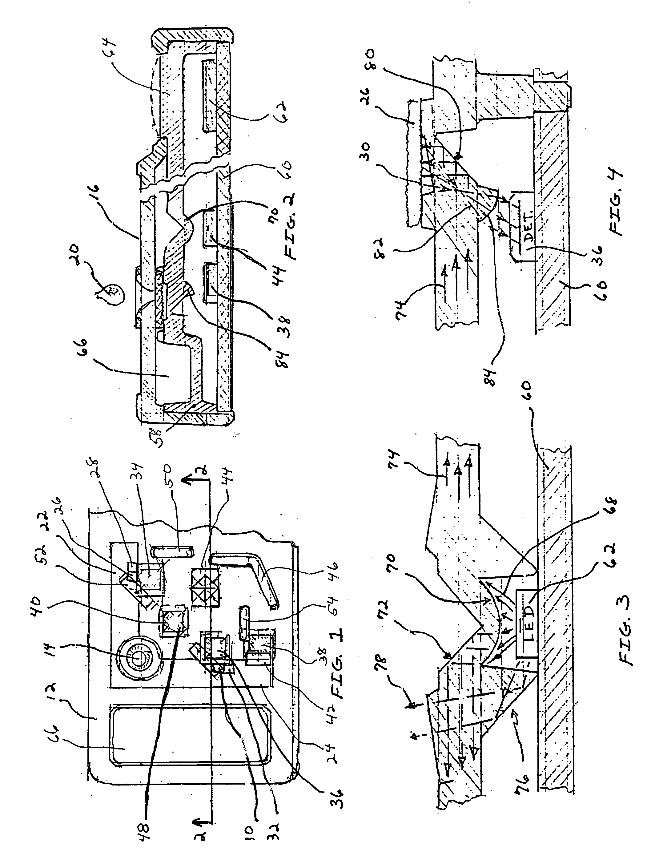
[0032] The present invention is preferably utilized in the disposable, single-use digital electronic instrument and assay devices described in detail in the above-identified patent applications previously incorporated by reference. However, the present invention can also be used in multiple-use or reusable devices which are compact for hand-held operation or easy portability. The present invention provides for the precise and accurate measurement of optical radiation reflected from one or more sampling areas located on one or more assay strips to quantitatively or qualitatively determine the presence or one or more selected analytes in a sample. The sampling areas can be one or more detection zones exhibiting a physically detectable change corresponding to the amount of the selected analyte or a reference zone which provides a control for comparison to the detection zone.

[0033] One embodiment of a single-use diagnostic device 10 of the present invention is illustrated in FIGS. 1 an...


PUM

PropertyMeasurementUnit
opticalaaaaaaaaaa
optical radiationaaaaaaaaaa
areaaaaaaaaaaa

Abstract

The present invention provides an optics assembly, a reflectometer, and a diagnostic device for providing quantitative measurement of optical radiation reflected from a sampling area on an assay matrix. The reflectometer includes an optical radiation source and a detector. The optical radiation source and the detector are mounted in a single plane. An optics assembly is configured to direct the illumination from the optical radiation source to the sampling area on the assay matrix and to direct the radiation diffusely reflected from the sampling area to the detector. The optics assembly is positioned over the face of the circuit board having the optical radiation source and detector mounted directly thereto. The present invention also provides a method for determining the presence of one or more selected analytes in a sample employing a plurality of sampling areas on one or more assay matrixes.

Description

RELATED APPLICATION [0001] The subject matter of this application is related to a disposable single-use digital electronic instrument that is entirely self-contained, including all chemistry reagents, as disclosed in U.S. application Ser. No. 08 / 111,347 entitled “Novel Disposable Electronic Assay Device” filed Aug. 24, 1993 by Michael P. Allen and now abandoned, U.S. application Ser. No. 08 / 455,236 entitled “Novel Disposable Electronic Assay Device” filed May 31, 1995 by Michael P. Allen, and U.S. application Ser. No. 08 / 512,844 entitled “Dry Reagent Particle Assay And Device Having Multiple Test Zones And Method Therefor” filed Aug. 9, 1995 by Joel M. Blatt and Michael P. Allen. The above applications have the same assignee as the present invention and are incorporated herein by reference in their entirety.FIELD OF THE INVENTION [0002] The present invention relates to a method and device for precisely measuring optical radiation reflected from a surface, preferably a sample-exposed...

Claims


Application Information

Patent Timeline
Patent Type & Authority Applications(United States)
IPC IPC(8): G01N21/47G01N21/25G01N21/86
CPCG01N21/253G01N21/8483
Inventor HEBERT, RAYMOND T.BLATT, JOEL M.WIDUNAS, JOSEPH T.
Owner POLYMER TECH SYST
Why Eureka
Try Eureka