Optical element for variable message signs

a technology of optical elements and message signs, applied in the direction of electrical equipment, instruments, lighting and heating equipment, etc., can solve problems such as deception of road users, and achieve the effects of simple and cost-effective structure, high luminosity, and low space consumption

Inactive Publication Date: 2006-04-13
DAMBACH WERKE
View PDF6 Cites 3 Cited by
  • Summary
  • Abstract
  • Description
  • Claims
  • Application Information

AI Technical Summary

Benefits of technology

[0009] Thus, it is the object of the present invention to provide an optical element for variable message signs which provides a very high luminosity in the desired ranges, wherein at the same time all regulations with respect to phantom light are fulfilled and the space consumption is held as low as possible with a simple and cost-effective structure.

Problems solved by technology

An essential aspect is the phantom light, i.e. sunlight impinging onto the LED, which is reflected by the LED and which may lead to deceptions to the road users when the position of the sun is unfavorable.
The disadvantage is the large distance between the converging lens and the dispersing lens that is necessary to avoid phantom light as well as the factual necessity to arrange a screen in the area of the focal spot of the converging lens so that the relevant regulations for light distribution and phantom light are fulfilled.

Method used


Image

  • Optical element for variable message signs
  • Optical element for variable message signs
  • Optical element for variable message signs

Examples


Embodiment Construction

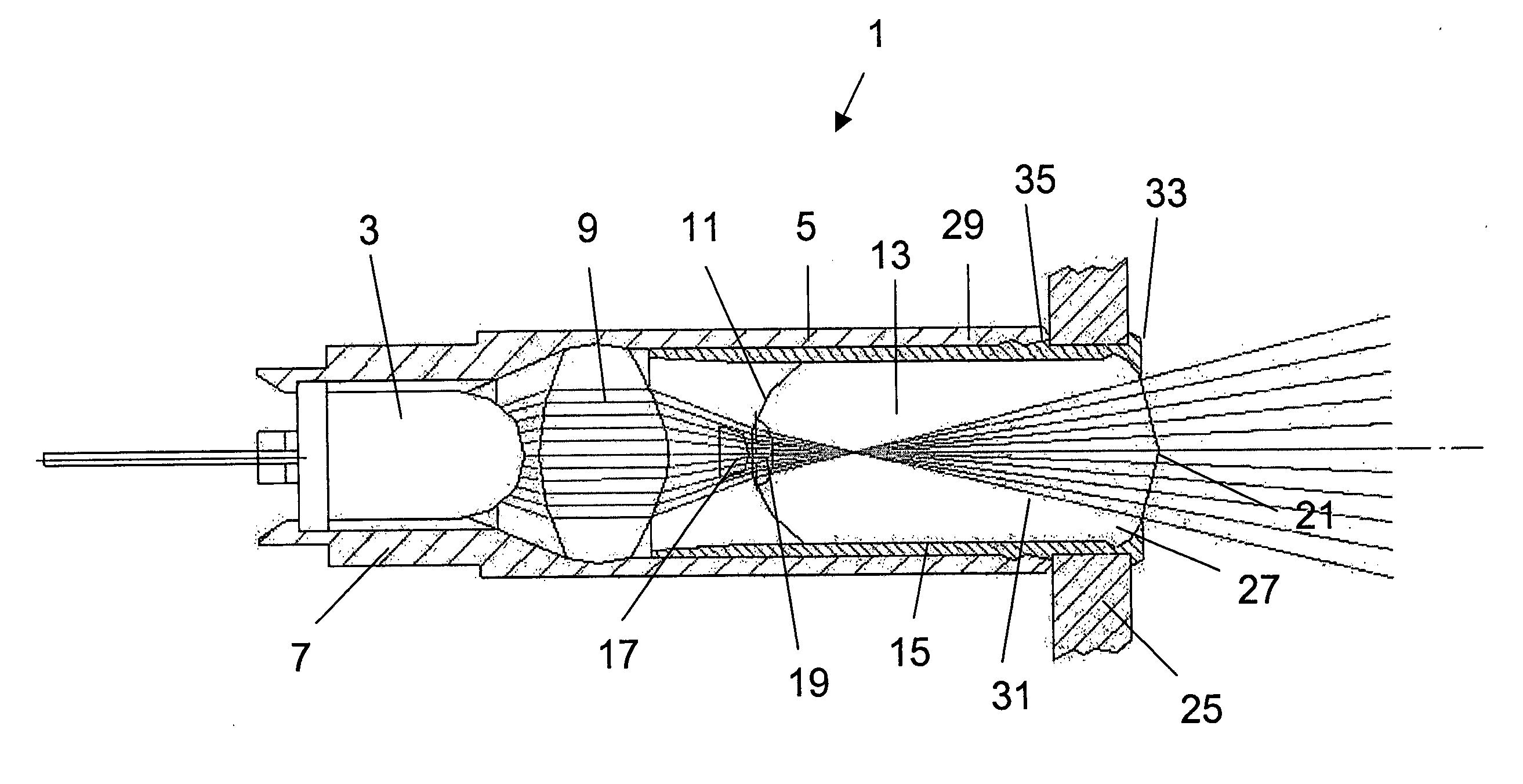
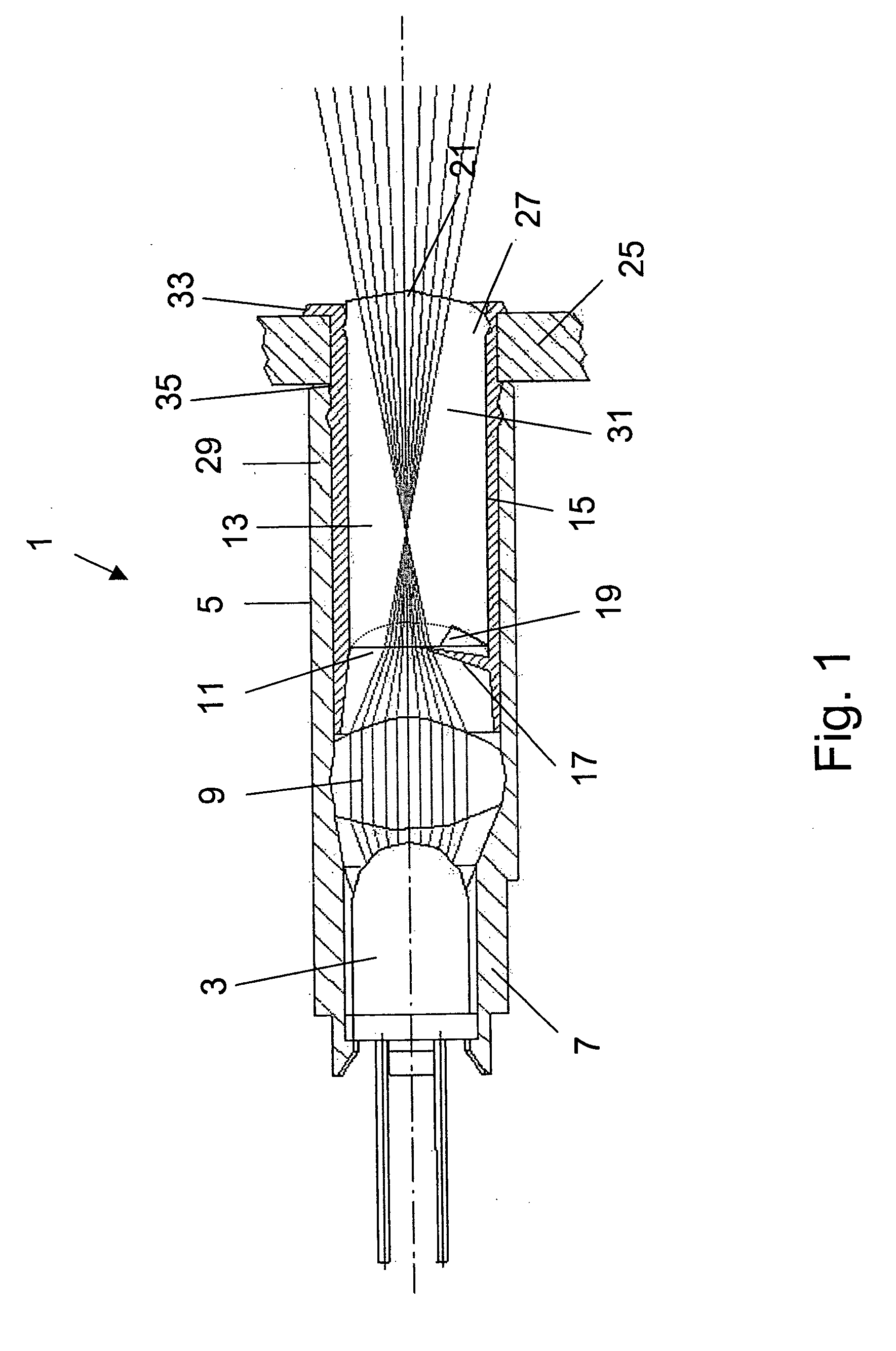
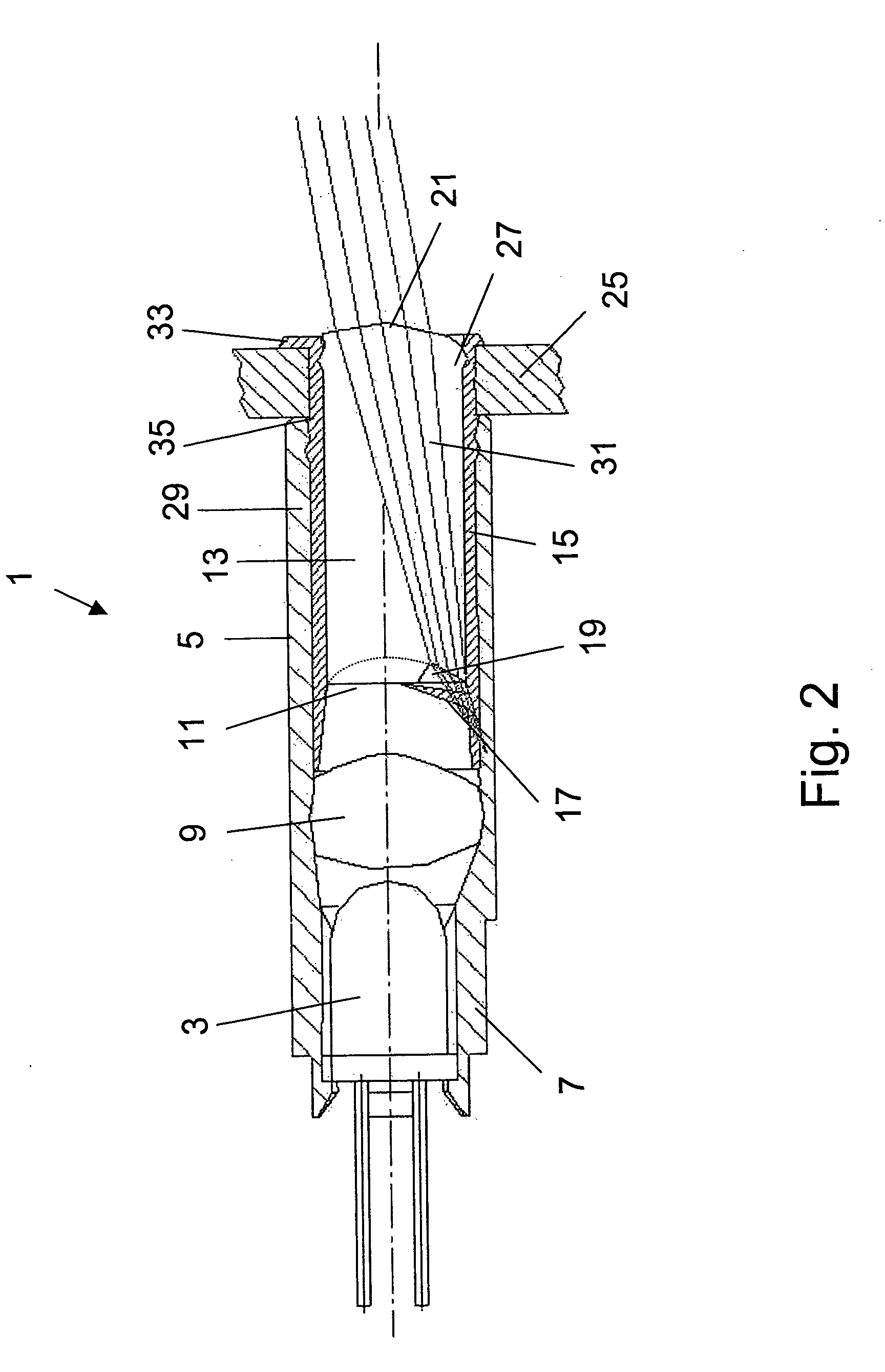
[0024]FIGS. 1 and 2 show the elements of the optical element for variable message signs according to the invention in a longitudinal section, and FIG. 3 shows them from the top in a cross section along the horizontal central plane of the arrangement. The optical element 1 has a light source 2, which is preferably formed as a light emitting diode (LED). The LED 3 provided with the usual terminals is accommodated and attached in a first oblong housing portion 5 close to the rear end 7 thereof. It is also possible to use LEDs mounted on printed circuit boards as illuminants. Moreover, a converging lens 9 is arranged in front of the LED 3 in the first housing portion 5 at a relative short distance to the LED 3, said converging lens bundling the light emitted by the LED 3 and further conducting it to a light entry surface 11 of a rod lens 13. The rod lens 13 is accommodated and fixed in a second oblong housing portion 15, wherein the light entry surface 11 of the rod lens 13 when inserti...


PUM


Abstract

An optical element for variable message signs includes an oblong housing, in which at least one light source as well as at least first and second lenses are arranged successively in the longitudinal direction of the housing. The lenses serve for defining the beam path of the light emitted by the light source in the irradiation direction, wherein the lens arranged closer to the light source is formed as a converging lens, and the lens arranged farther away from the light source is formed as a rod lens.

Description

RELATED APPLICATION [0001] This application claims the benefit of EP 04 023 304.1, filed Sep. 30, 2004, the contents of which are incorporated herein. FIELD OF THE INVENTION [0002] The present invention refers to an optical element for variable message signs. [0003] Variable message signs serve in many places for regulating the road traffic in that, depending on the traffic density and given general conditions, they are capable of displaying certain road signs that may be shown as symbols or characters. A variable message sign is equipped with a matrix-like arrangement of optical elements which compose the overall display. A light point corresponds to each optical element, wherein said light point is supposed to be perceived by the driver from a far distance so that the road traffic can safely be guided. [0004] The invention relates to a cooling device for preferably large-format units which are to be cooled and which have a high thermal dissipation. BACKGROUND OF THE INVENTION [000...

Claims


Application Information

Patent Timeline
Patent Type & Authority Applications(United States)
IPC IPC(8): F21S6/00
CPCF21V5/04F21W2111/02G09F9/33
Inventor ESCHBACH, BERND
Owner DAMBACH WERKE
Why Eureka
Try Eureka