Stereolithographic apparatus

a technology of stereolithography and lithography chamber, which is applied in the field of stereolithography chamber, can solve the problems of system difficulties, shrinkage, resolution, accuracy, etc., and achieve the effects of easy and fast changing of resin vats, simple resin vats, and easy change over of resin vats

Inactive Publication Date: 2006-04-13
3D SYST INC
View PDF10 Cites 76 Cited by
  • Summary
  • Abstract
  • Description
  • Claims
  • Application Information

AI Technical Summary

Benefits of technology

[0013] It is an advantage of the present invention that multiple resins, including differently colored resins, can be utilized concurrently in a stereolithography system to produce three-dimensional objects with different physical properties.
[0014] It is another advantage of the present invention that a simple resin vat and elevator leg mounting system is employed to permit easy and fast changing of resin vats or material containers and changing from single chambered vat operation to multiple chambered vat operation or vice versa.
[0015] It is still another advantage of the present invention that no cleaning of the stereolithography system parts is required between change over of vats.
[0016] These and other aspects, features, and advantages are obtained by the present invention through the use of a multiple chambered resin vat and a quick disconnect mounting system to permit concurrent use of multiple photopolymer build materials and easy change over of resin vats in a stereolithography system.

Problems solved by technology

Such systems have encountered and had to overcome difficulties relating to shrinkage, curl and other distortions, as well as resolution, accuracy, and difficulties in producing certain object shapes.

Method used


Image

  • Stereolithographic apparatus
  • Stereolithographic apparatus
  • Stereolithographic apparatus

Examples


Embodiment Construction

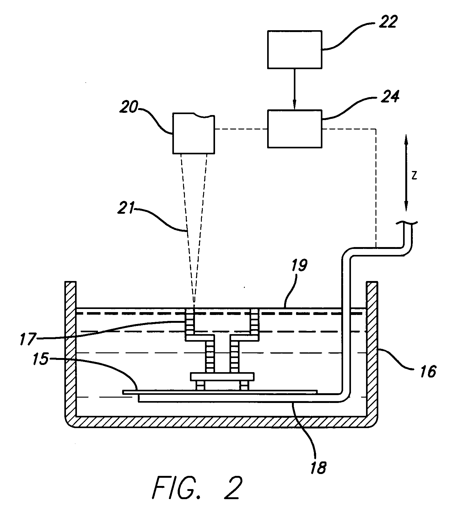
[0027] Stereolithography typically involves the layer by layer build-up of articles from a vat or container of liquid monomer. Stereolithography parts are preferably built on structures known as supports rather than directly on an elevator platform that moves the build object or part up and down as successive layers or laminae are formed during the stereolithography process. The vat of liquid photopolymer material provides a fresh material to create new layers as the object is built.

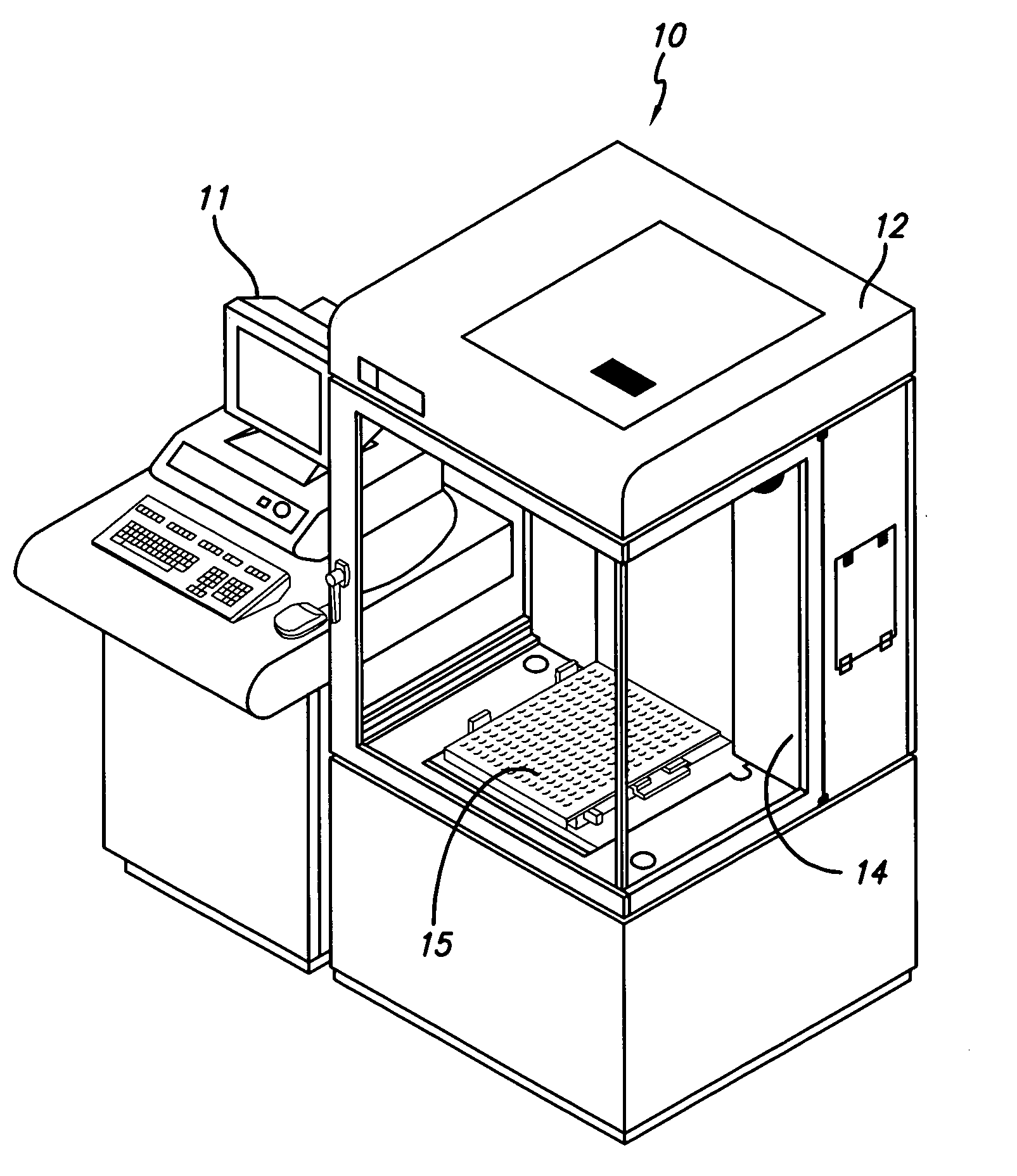
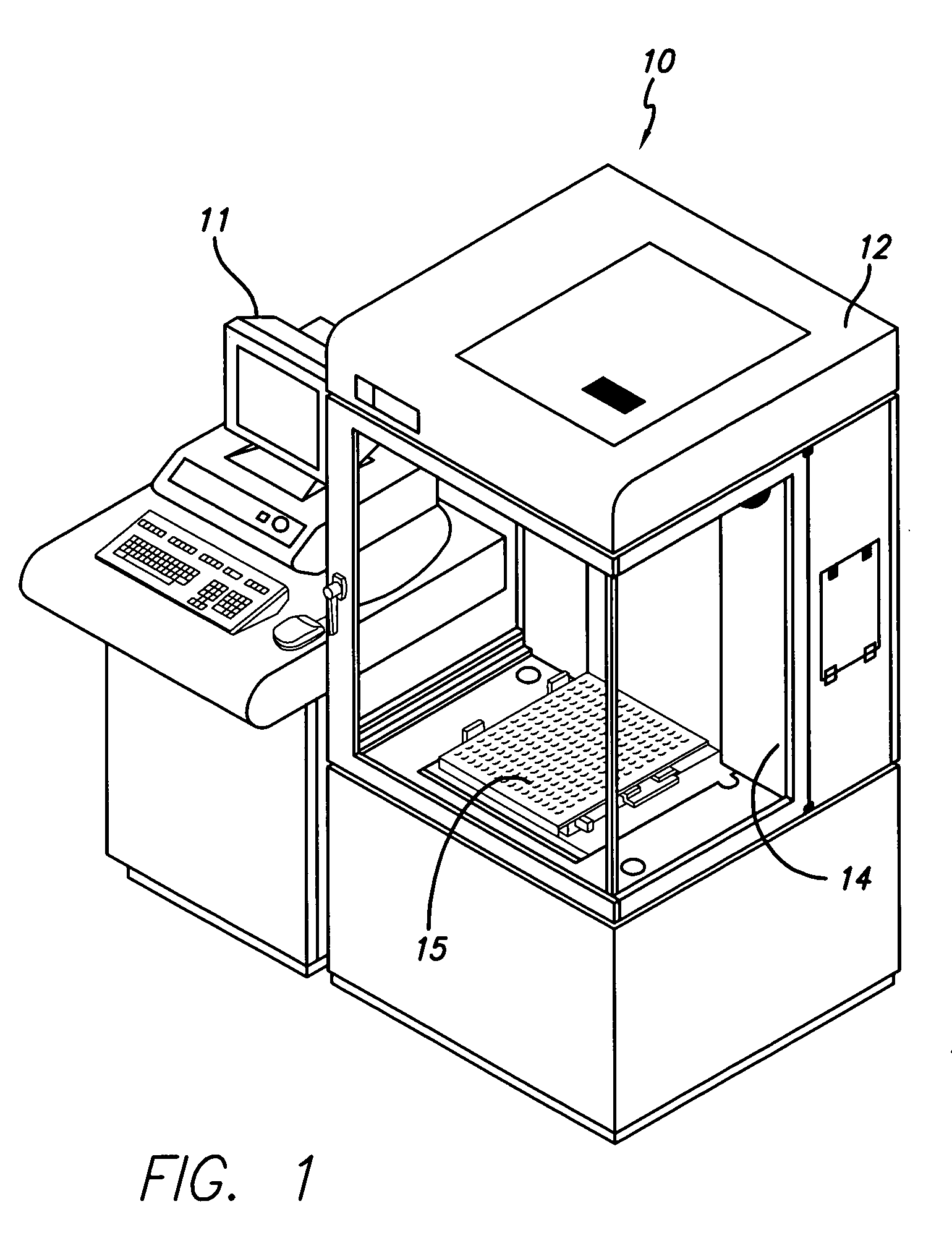
[0028] A typical stereolithography system is represented by the numeral 10 shown in FIG. 1. Such a system is offered commercially by 3D Systems, Inc. of Valencia, Calif. as the Viper Si2™ SLA® system. The system 10 includes a computer console 11 with a control computer, computer terminal, and monitor. The system 10 also has a laser housing 12 that includes a laser, mirrors, crystal and other components of the laser system of the type described in U.S. Pat. No. 6,157,663 to Wu et al. and assigned to the ...


PUM

PropertyMeasurementUnit
depthaaaaaaaaaa
energyaaaaaaaaaa
processingaaaaaaaaaa

Abstract

An improved stereolithography apparatus for forming three-dimensional objects using multiple chambered resin vats and a quick disconnect mounting system to permit concurrent use of multiple photopolymer build materials and easy change over of resin vats is disclosed. The apparatus permits easy change over from multiple chambered vat use to single chamber vat use and vice versa or change over between multiple chambered vats.

Description

FIELD OF INVENTION [0001] The present invention is directed to a stereolithographic apparatus for forming three-dimensional objects on a layer-by-layer basis and, more particularly, is directed to an apparatus having multiple resin vats or containers to permit more than one part location to be utilized during the building of stereolithographic objects and to permit easy and rapid change over of multiple resin vats or containers to a single vat or container, or between multiple vats by using an improved mounting system. BACKGROUND OF THE INVENTION [0002] In recent years, many different techniques for the fast production of three-dimensional models have been developed for industrial use. These are sometimes referred to as rapid prototyping and manufacturing (“RP&M”) techniques. In general, rapid prototyping and manufacturing techniques build three-dimensional objects layer by layer from a working medium utilizing a sliced data set representing cross-sections of the object to be formed...

Claims


Application Information

Patent Timeline
Patent Type & Authority Applications(United States)
IPC IPC(8): B29C35/08B29C41/02
CPCB29C67/0066B29L2031/7532B29C64/135B33Y30/00B33Y40/00B33Y70/00
Inventor HOLMBOE, SCOTT B.REYNOLDS, GARY L.STONESMITH, MATTHEW K.HULL, CHARLES W.REICHENTAL, ABRAHAM N.
Owner 3D SYST INC
Why Eureka
Try Eureka