Gas burner and method for controlling the same

a technology of burners and gas, applied in the direction of burners, combustion types, combustion regulation, etc., can solve the problems of reducing stability, overheating of glass, unstable flames, etc., and achieve the effect of improving combustion efficiency

Inactive Publication Date: 2006-04-13
LG ELECTRONICS INC
View PDF10 Cites 18 Cited by
  • Summary
  • Abstract
  • Description
  • Claims
  • Application Information

AI Technical Summary

Benefits of technology

[0019] An object of the present invention is to provide a gas burner and a method for controlling the same in which stable use is possible.
[0020] Another object of the present invention is to provide a gas burner and a method for controlling the same in which combustion efficiency is improved.

Problems solved by technology

If the air flow is excessively supplied, flame becomes unstable to fail to normally supply heat.
Since the related art burner is operated at a constant air-fuel ratio, the glass is overheated because no separate control device is provided if the temperature of the glass increases at a reference value or greater, thereby reducing stability.
In addition, heat loss increases as the temperature of the glass increases at a reference value or greater.

Method used


Image

  • Gas burner and method for controlling the same
  • Gas burner and method for controlling the same
  • Gas burner and method for controlling the same

Examples


first embodiment

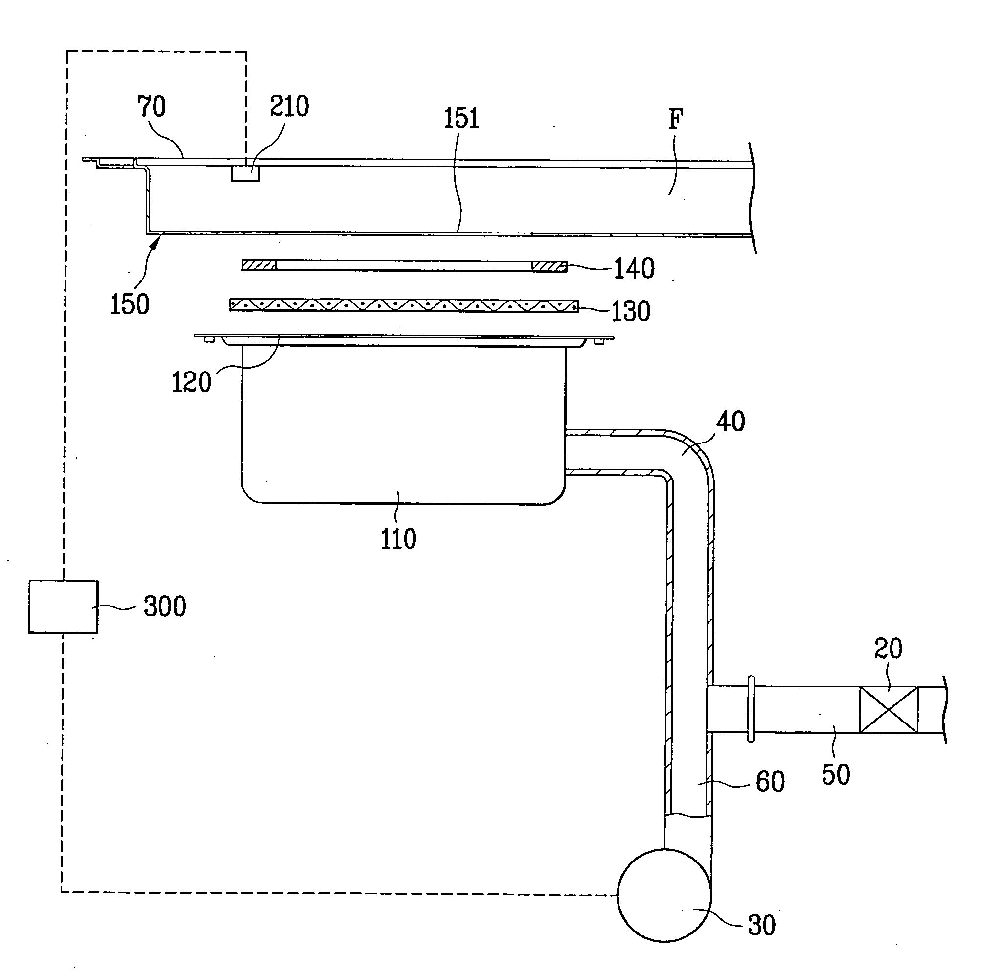
[0043] A gas burner according to the present invention will be described with reference to FIG. 3 and FIG. 4.

[0044] The gas burner according to the first embodiment of the present invention includes a burner body 100 burning a mixture gas of gas fuel and air, a temperature sensor 210 measuring a temperature of a glass 70 provided on the burner body 100, and a control part 300 controlling air flow supplied to the burner body 100 based on the measured value of the temperature sensor 210.

[0045] A mixing tube 40 is provided at one side of the burner body 100 and supplies the mixture gas to the burner body 100. The mixing tube 40 is connected with a gas supplying tube 50 and an air supplying tube 60. The gas supplying tube 50 supplies gas fuel and the air supplying tube 60 supplies air.

[0046] The gas supplying tube 50 and the air supplying tube 60 are respectively connected with a gas supplying valve 20 and an air supplying fan 30.

[0047] The burner body 100 includes a burner chamber 1...

second embodiment

[0065] A method for controlling a gas burner according to the present invention will be described with reference to FIG. 6 and FIG. 7.

[0066] In the second embodiment unlike the first embodiment, a pressure sensor 220 is provided to measure inner pressure of the gas burner. In more detail, the pressure sensor 220 is provided inside the air supplying tube 60 and is connected with the control part 300 provided at one side of the gas burner.

[0067] The control part 300 controls the RPM of the air supplying fan 30 based on the pressure measured by the pressure sensor to control the air flow.

[0068] The position of the pressure sensor may be selected optionally inside the gas burner. The present invention is not limited to the aforementioned first embodiment. Both the pressure sensor and the temperature sensor may be provided. A sensor that measures a separate characteristic value may be provided. Examples of the characteristic value include speed of exhaust gas, quantity of exhaust gas, ...


PUM


Abstract

Disclosed are a gas burner and a method for controlling the same in which stable use is possible and combustion efficiency is improved. The gas burner includes a burner body burned by a mixture gas of gas fuel and air, a gas supplying valve supplying the gas fuel to the burner body through a gas supplying tube connected with the burner body, an air supplying fan supplying the air to the burner body through an air supplying tube connected with the burner body, and a control part controlling air flow supplied to the burner body by controlling revolution per minute (RPM) of the air supplying fan. Since an optimal air-fuel ratio can be maintained by controlling the RPM of the air supplying fan, combustion efficiency can be increased. Since a temperature of a glass can be maintained properly, life span of the gas burner can be increased and its stable use is possible.

Description

[0001] This application claims the benefit of Korean Application No. P2004-081260, filed on Oct. 12, 2004, and Korean Application No. P2004-081261, filed on Oct. 12, 2004, which are hereby incorporated by reference as if fully set forth herein. BACKGROUND OF THE INVENTION [0002] 1. Field of the Invention [0003] The present invention relates to a gas burner and a method for controlling the same, and more particularly, to a gas burner and a method for controlling the same in which stable use is possible and combustion efficiency is improved. [0004] 2. Background of the Related Art [0005] Generally, a gas burner is designed to generate heat for heating, cooking, and the like by burning gas fuel such as LPG and LNG. The gas burner is manufactured in various types depending on its purpose of use. [0006] Hereinafter, a related art gas burner will be described with reference to the accompanying drawings. [0007]FIG. 1 illustrates a related art gas burner, and FIG. 2 is a graph illustrating ...

Claims


Application Information

Patent Timeline
Patent Type & Authority Applications(United States)
IPC IPC(8): F23N5/00F23N3/00F23N5/02
CPCF23N3/002F23N5/022F23N2025/06F23N2025/16F23N2033/08F23N2225/06F23N2225/16F23N2233/08F23D14/12
Inventor KIM, YOUNG SOOJUNG, DAE HEELEE, DAE RAE
Owner LG ELECTRONICS INC
Why Eureka
Try Eureka