Array beamforming with wide nulls

a beamforming array and null technology, applied in the field of beamforming, can solve the problems of multipath interference, difficult and expensive to form a narrow beam, and become increasingly difficult to avoid interference between wireless clients

Inactive Publication Date: 2006-04-13
CISCO TECH INC
View PDF22 Cites 14 Cited by
  • Summary
  • Abstract
  • Description
  • Claims
  • Application Information

AI Technical Summary

Problems solved by technology

As the number of clients in a network continues to increase, it becomes increasingly hard to avoid interference between wireless clients, even when using an adaptive antenna array.
Also, multipath interference can result from reflections and / or diffraction of the client' signal off metal within the building in which the WLAN operates.
In practice, it is difficult and expensive to form a narrow beam, requiring adaptive arrays with more elements and a high level of precise calibration.
However, such arrays are undesirably expensive, due to the level of testing and calibration.
Also, with potential sales volumes of several hundred thousand antenna arrays per year, such handling slows down production in addition to adding to the expense, thereby further reducing production efficiency.

Method used


Image

  • Array beamforming with wide nulls
  • Array beamforming with wide nulls
  • Array beamforming with wide nulls

Examples


Embodiment Construction

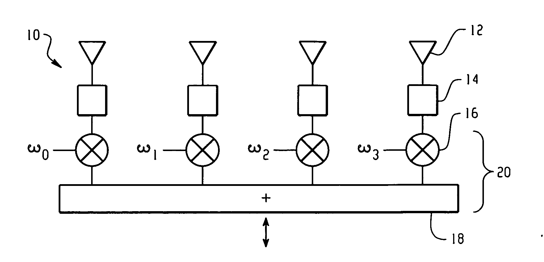
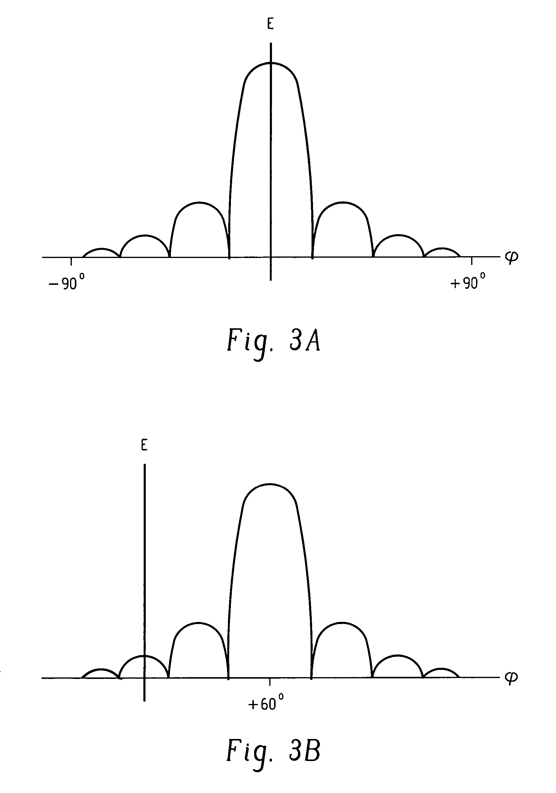
[0013] In the present invention, signal interference is avoided by the method and implementation of the present invention by steering wide, deep nulls in the direction of interference, e.g. multipath sources or interfering clients and steering rudimentary beams in the desired directions. By creating wide nulls and beams with the present invention, normal manufacturing methods suffice and the positional error of the array can be accommodated, and an uncalibrated antenna array can be employed. In this way, the expensive and time consuming steps of array calibration and testing can be eliminated, thereby considerably reducing expense and increasing efficiency.

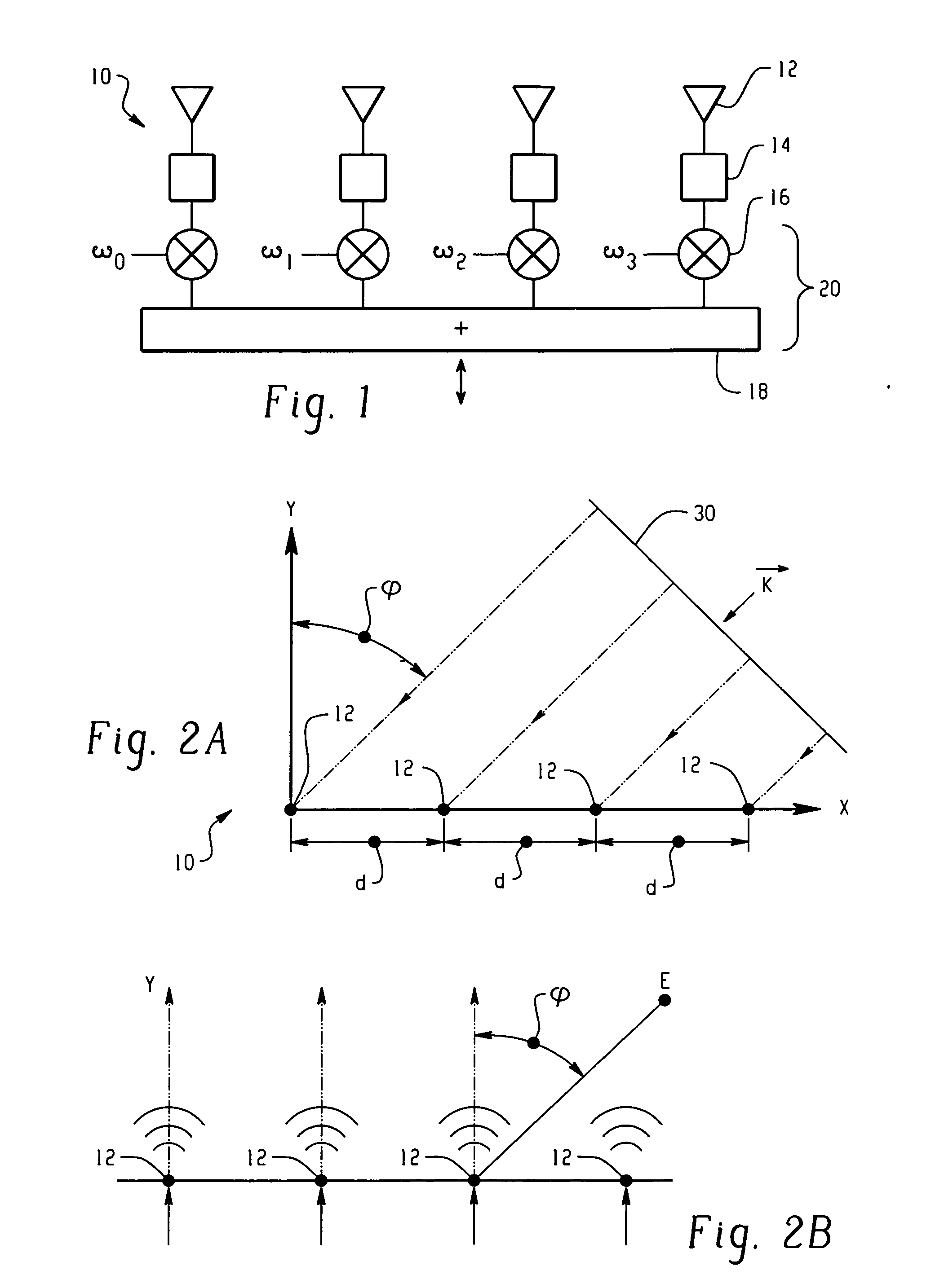
[0014] The present invention uses a novel technique of subspace beamforming and wide-null forming using the nominal array manifold to compute suitable weighting factors, for the antenna elements in a steerable, directional antenna array. The present invention can be used with a one-dimensional linear array, or with a two-dimensio...


PUM


Abstract

A method and implementation of wireless communication are disclosed in which wireless signals are exchanged between at least one remote client and a directional antenna array associated with a wireless network, wherein the directional antenna array includes a plurality of antenna elements. A statistical matrix analysis is performed for each of the at least one client and the antenna array, in order to locate angles associated with directions of each client with respect to the antenna array. Values are determined for weighting factors for RF signals of each of the respective plurality of antenna elements, so as to create predetermined phase differences between the signals of the plurality of antenna elements. The predetermined phase differences are used to direct at least one null toward at least one source of interference, so as to avoid signal interference.

Description

CROSS REFERENCE TO RELATED APPLICATIONS [0001] This application is a continuation of U.S. patent application Ser. No. 10 / 225,948 filed Aug. 22, 2002, now U.S. Pat. No. 6,970,722.BACKGROUND OF THE INVENTION [0002] The present invention is directed to the field of beamforming, particularly as used with an adaptive antenna array for a wireless telecommunications system, e.g. a wireless local area network (WLAN). In previous-type WLAN systems, it had been sufficient to communicate with wireless clients using one or more omnidirectional antennas. In such a previous-type scheme, wireless clients gain access to the WLAN by operating on different frequency bands and / or time-sharing over the same set of frequency bands. [0003] As the number of clients in a WLAN increases, with resulting increased demands for WLAN access, it becomes necessary to “manage space,” i.e. spatially isolate communications between clients distributed over a geographic area. To this end, it has become common to employ...

Claims


Application Information

Patent Timeline
Patent Type & Authority Applications(United States)
IPC IPC(8): H04B1/02H04M1/00H01Q3/42
CPCH01Q3/42
Inventor LEWIS, MICHAEL E.
Owner CISCO TECH INC
Why Eureka
Try Eureka