Visualization method and apparatus for logic verification and behavioral analysis

a visualization method and logic verification technology, applied in the direction of instrumentation, program control, cad circuit design, etc., can solve the problems of large-scale simulation that requires a significant amount of processing time, inaccurate or misunderstood specifications, and the frequency of failures tends to decreas

Inactive Publication Date: 2006-04-13
GLOBALFOUNDRIES INC
View PDF6 Cites 19 Cited by
  • Summary
  • Abstract
  • Description
  • Claims
  • Application Information

AI Technical Summary

Benefits of technology

[0010] According to the present invention, an operation which is highly likely to cause a fault can be detected and noticed, thereby enabling a logic circuit to be debugged efficiently.

Problems solved by technology

However, a large-scale simulation requires a significant amount of processing time.
Such failures result from the presence of an item missing from verification items for each component or logic function, a factor such that specifications are inaccurate or misunderstood, an unexpected operation caused by a combination of the component parts, etc.
However, as verification process using hardware progresses, the frequency of failure occurrences tends to decreases to, for example, once per several days, and it becomes difficult to specify in advance the timing at which failures will occur.
When the time series data of all the signals is recorded in order to appropriately observe failures as described above, the amount of data becomes too large for practical analysis.

Method used


Image

  • Visualization method and apparatus for logic verification and behavioral analysis
  • Visualization method and apparatus for logic verification and behavioral analysis
  • Visualization method and apparatus for logic verification and behavioral analysis

Examples


Embodiment Construction

[0023] While the invention will be described below with reference to a preferred embodiment or embodiments, it will be understood by those skilled in the art that various changes may be made and equivalents may be substituted for elements thereof without departing from the scope of the invention. In addition, many modifications may be made to adapt a particular situation or material to the teachings of the invention without departing from the essential scope thereof. Therefore, it is intended that the invention not be limited to the particular embodiment disclosed as the best mode contemplated for carrying out this invention, but that the invention will include all embodiments falling within the scope of the appended claims.

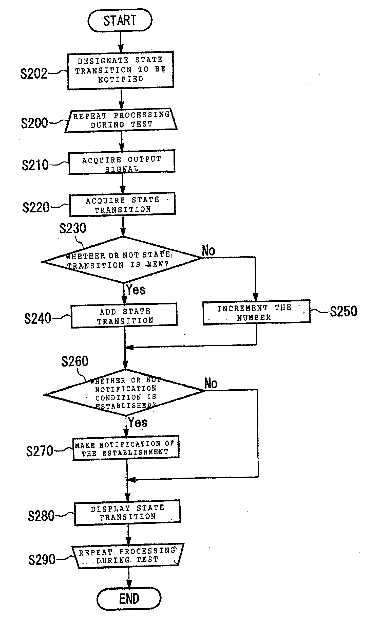
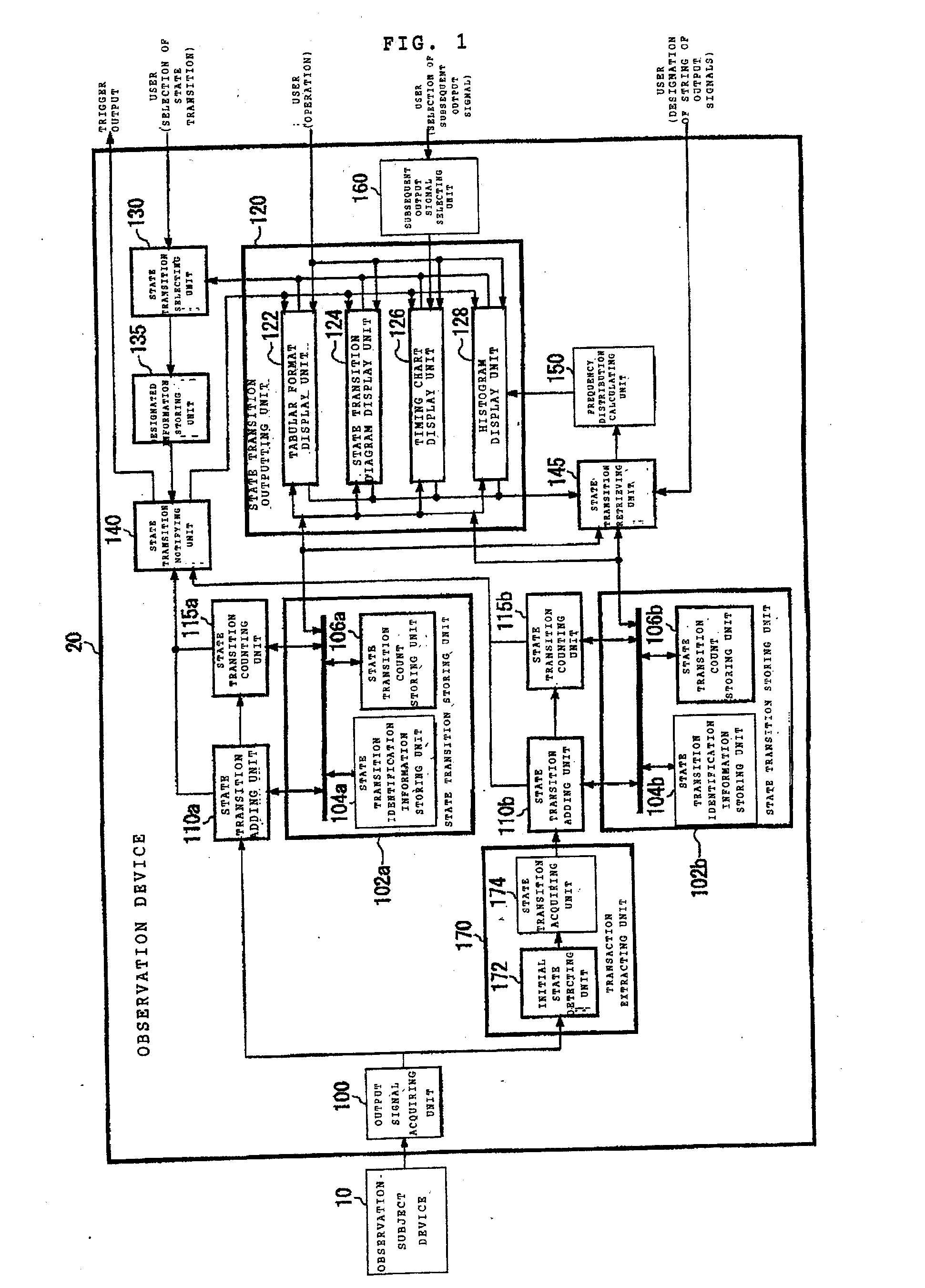
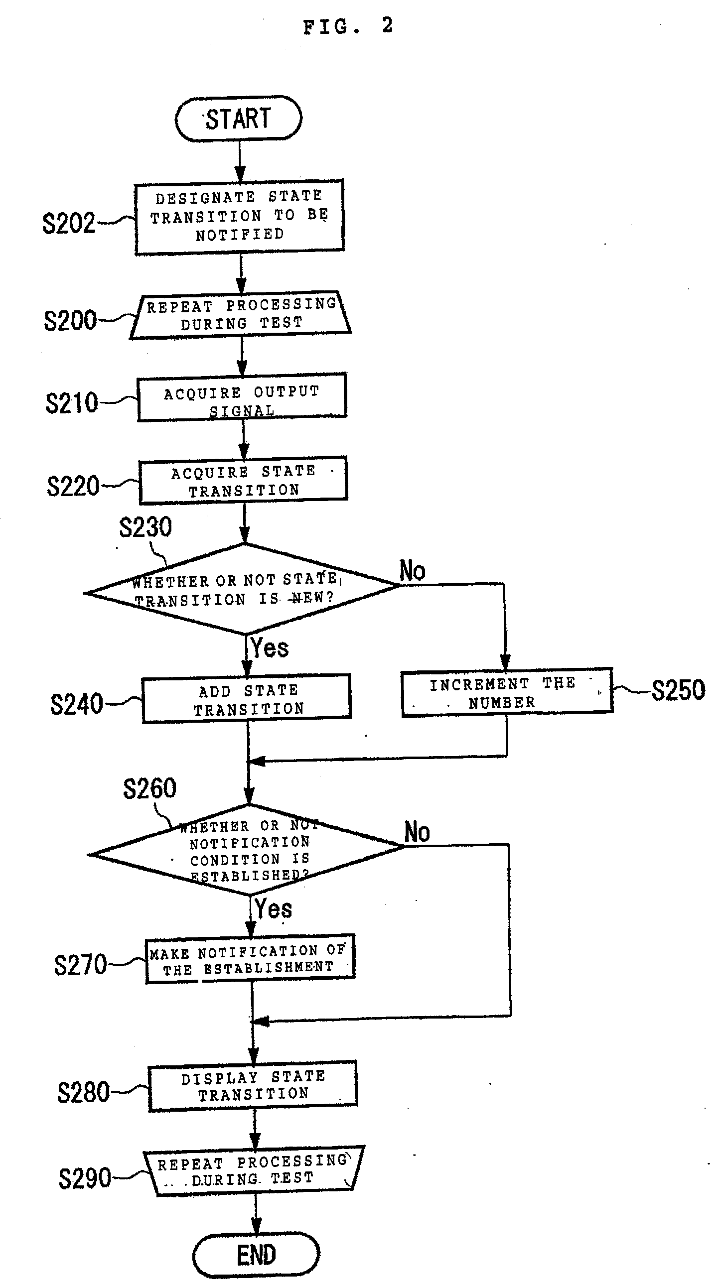
[0024]FIG. 1 shows a configuration of an observation device 20 according to a preferred embodiment together with an observation-subject device 10. The observation-subject device 10 is a logic device to be observed, for example, a hardware emulator composed of an...


PUM


Abstract

A logic verification tool detects and flags a logic operation with high probability to cause a fault in an electronic system. An efficient logic debug method utilizes a partial sequence of signal outputs and state transitions to extrapolate a verification result with equivalent robustness to full regression testing.

Description

FIELD OF THE INVENTION [0001] The present invention relates to an observation device, an observation method for logic verification and behavioral analysis. The present invention relates particularly to an observation device, an observation method and a program thereof for receiving a signal which is outputted by a logic unit to be observed, and for observing an operation of the logic unit to be observed. BACKGROUND OF THE INVENTION [0002] Techniques for assisting the debugging of a designed logic circuit have been previously disclosed by the following patent literature. United States Patent No. 5,576,979 discloses a method of generating a timing diagram for an electronic circuit under test. A technique disclosed by U.S. Pat. No. 6,289,489 makes it possible to cause a hardware description language (HDL) and a state of a logic circuit, which is displayed by a graphical user interface (GUI), to correspond to each other, thereby enabling a cross reference to be made between the hardware...

Claims


Application Information

Patent Timeline
Patent Type & Authority Applications(United States)
IPC IPC(8): G06F17/50G06F11/00G06F9/45
CPCG01R31/318357G06F17/5022G06F30/33
Inventor OHBA, NOBUYUKITAKANO, KOHJI
Owner GLOBALFOUNDRIES INC
Why Eureka
Try Eureka