Gas generator

Inactive Publication Date: 2006-04-20
JOYSON SAFETY SYST ACQUISITION LLC
View PDF7 Cites 35 Cited by
  • Summary
  • Abstract
  • Description
  • Claims
  • Application Information

AI Technical Summary

Benefits of technology

[0005] Various gas generant formulations have been developed in which the particulates resulting from combustion of the gas generant are substantially eliminated or significantly reduced. To solve the problems of reducing airbag inflator size, weight, cost and efficiency, the present invention obviates the need for a conventional filter by appropriate selection of a state of the art gas generant, or a smokeless gas generant if desired, and by incorporation of a baffle tube which cools the combustion gases prior to dispersal of the gases into an airbag. Obviating the need for a filter in an inflator allows the inflator to be simpler, lighter, less expensive and easier to manufacture.
[0007] The baffle tube also provides an extended travel path for combustion gases flowing from the propellant chamber to discharge nozzles in the inflator, thereby allowing time for complete combustion of the gas generant in the inflator.
[0008] In another embodiment, the present invention provides orifices formed in the inner annulus, the outer annulus, and the walls. The walls and the orifices formed in the walls divide the baffle into a series of adjacent fluidly-communicating baffle chambers. Gases flow out of the inner annulus orifice, then sequentially through the fluidly-communication baffle chambers, the out of the baffle via the outer annulus orifice. This arrangement enables the degree of cooling of the gases to be controlled.

Problems solved by technology

Inhalation by a vehicle occupant of particulates generated by propellant combustion-during airbag-activation can be hazardous.
However, the wire mesh filter assembly increases the weight and expense of the inflator.
In addition, due to factors such as spatial constraints within the gas generator / inflator and / or the type of gas generant used, combustion of the gas generant may be incomplete when combustion products exit the combustion chamber, resulting in flaming of the combustion products as the gases exit the combustion chamber and enter the wire mesh filter.
The porous structure of the wire mesh filter may be unable to contain the flaming combustion products.

Method used


Image

  • Gas generator
  • Gas generator
  • Gas generator

Examples


Embodiment Construction

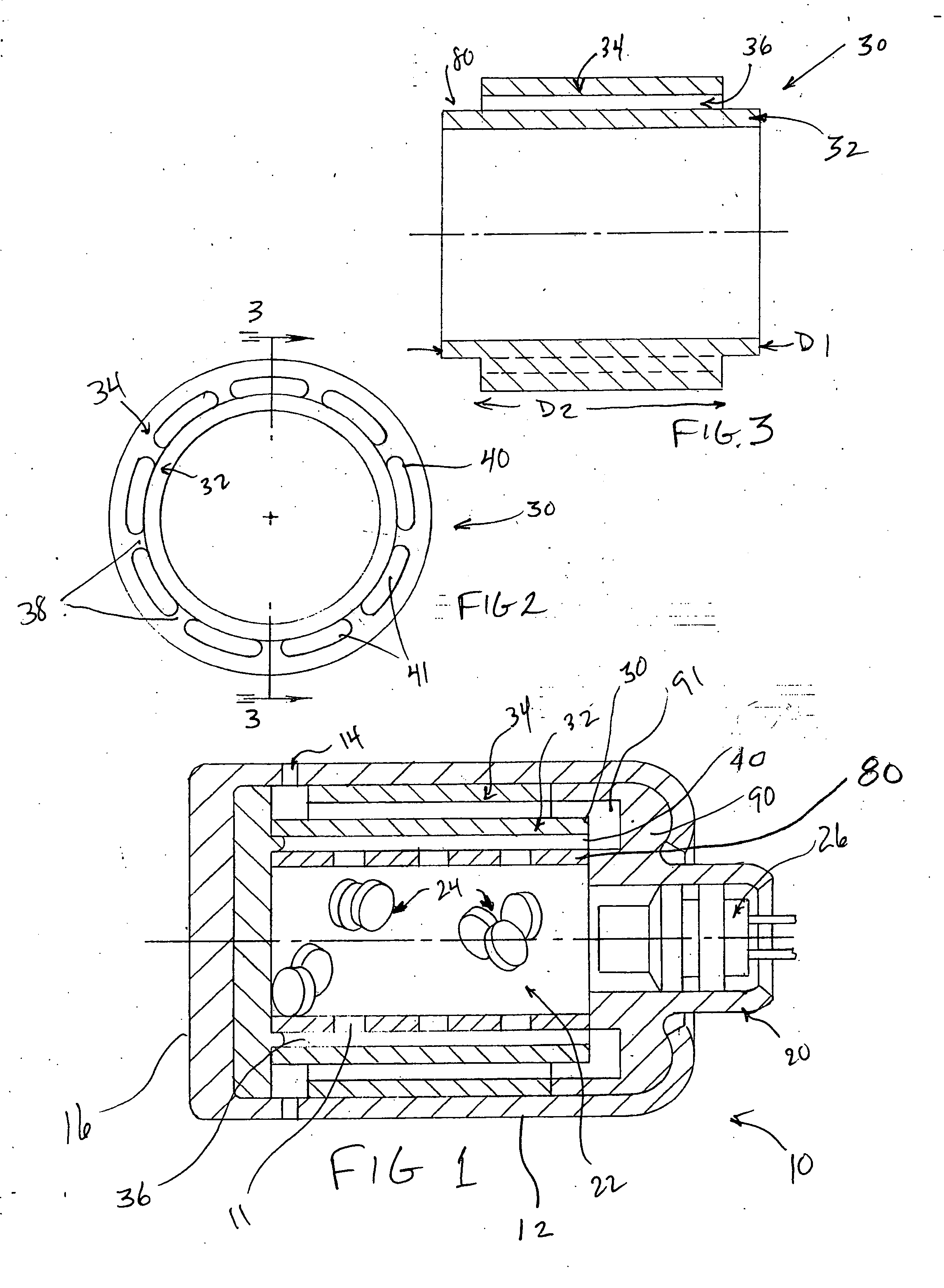
[0019]FIG. 1 shows a gas generator or inflator 10, in accordance with one embodiment of the invention. Inflator 10 includes a housing 12, for example, an aluminum forging. In this embodiment, housing 12 is provided with at least one gas discharge nozzle 14, or a plurality of gas discharge nozzles 14 arranged in at least one circumferentially and homolaterally extending row. Nozzles 14 may be circumferentially spaced apart substantially evenly. Housing 12 has an integral end closure 16 at one end and an end closure 20 at the opposite end that is crimped in place. A perforated propellant chamber 22 is centrally and longitudinally disposed within housing 12 for containment of propellant grains 24. Propellant chamber 22 has a longitudinal axis L.

[0020] The inside of the propellant chamber 22 may be provided with a burst foil covering perforations 11 of chamber 22 to facilitate pressure buildup and flame front propagation through propellant grains 24. End closure 20 accepts an electrica...


PUM


Abstract

The present invention provides an inflator for an inflatable restraint system in an automobile. The inflator includes an elongate inflator body containing a baffle tube that cools gases as they are shunted therethrough upon gas generator activation.

Description

BACKGROUND OF THE INVENTION [0001] The present invention relates generally to inflators for use in inflatable occupant restraint systems in motor vehicles and, more particularly, to baffle systems for replacing filters used in inflators to remove particulates from combustion gases and to cool the gases. [0002] Installation of inflatable occupant restraint systems, such as airbags, as standard equipment in all new vehicles has intensified the search for smaller, lighter and less expensive restraint systems. Accordingly, since the inflator used in such systems tends to be the heaviest and most expensive component, there is a need for a lighter and less expensive inflator. [0003] A typical inflator includes cylindrical steel or aluminum housing having a diameter and length related to the vehicle application and characteristics of a gas generant propellant contained therein. Inhalation by a vehicle occupant of particulates generated by propellant combustion-during airbag-activation can ...

Claims


Application Information

Patent Timeline
IPC IPC(8): B60R21/26
CPCB60R21/2644
Inventor BLACKBURN, JEFFERY S.
Owner JOYSON SAFETY SYST ACQUISITION LLC
Why Eureka
Try Eureka