Toroidal AC motor

a synchronous motor and torque technology, applied in the direction of synchronous motors, magnetic circuit rotating parts, magnetic circuit shapes/forms/construction, etc., can solve the problems of reducing the efficiency of the motor, and widening the commercialization of the synchronous motor. , to achieve the effect of expanding the storage of magnetic energy em and prolonging the gap length

Inactive Publication Date: 2006-04-20
PATENT
View PDF18 Cites 54 Cited by
  • Summary
  • Abstract
  • Description
  • Claims
  • Application Information

AI Technical Summary

Benefits of technology

[0009] The design of the toroidal AC motor permits a high pole number NP and consequent high torque without incurring unacceptable thermal losses. The copper cross-sectional area AC of the winding is increased to permit a longer gap length lg and thus expanded storage of magnetic energy EM. In this regard, the toroidal motor has a stator with a plurality of U-shaped stator poles and a winding disposed within the “U” of each of the poles. The winding is generally annular with the poles being placed around the outer circumference thereof. The motor further includes a rotor having a plurality of rectangular shaped poles disposed in a generally circular configuration. Each of the rotor poles corresponds to one of the stator poles. The stator is configured as a ring which surrounds the rotor and the rotor poles. The rotor is held in position by end-rings and bearings such that the rotor can rotate within the stator. The rotor further includes a shaft extending axially therefrom which turns in response to exciting the stator with the winding.

Problems solved by technology

However, the two main drawbacks preventing widespread commercialization of the AC synchronous motor are that there must be zero starting torque at a fixed input frequency and that the motor must utilize slip rings and brushes for rotor excitation.
However, both of the methods decrease the efficiency of the motor.
As such, efficiency drops off as poles increase and as stored magnetic energy increases because resistive losses quickly outstrip torque gain achieved by increasing these two variables.

Method used


Image

  • Toroidal AC motor
  • Toroidal AC motor
  • Toroidal AC motor

Examples


first embodiment

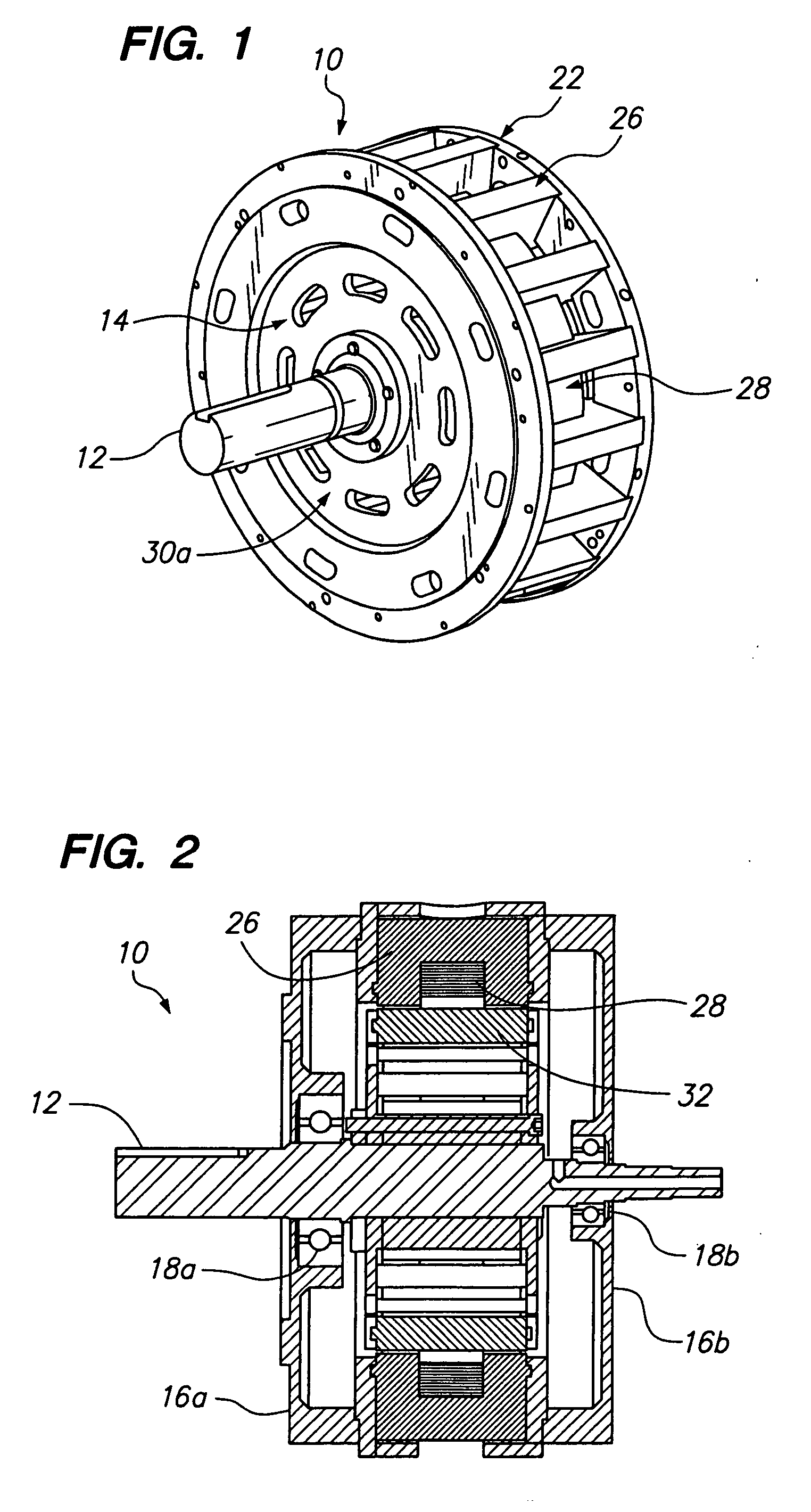
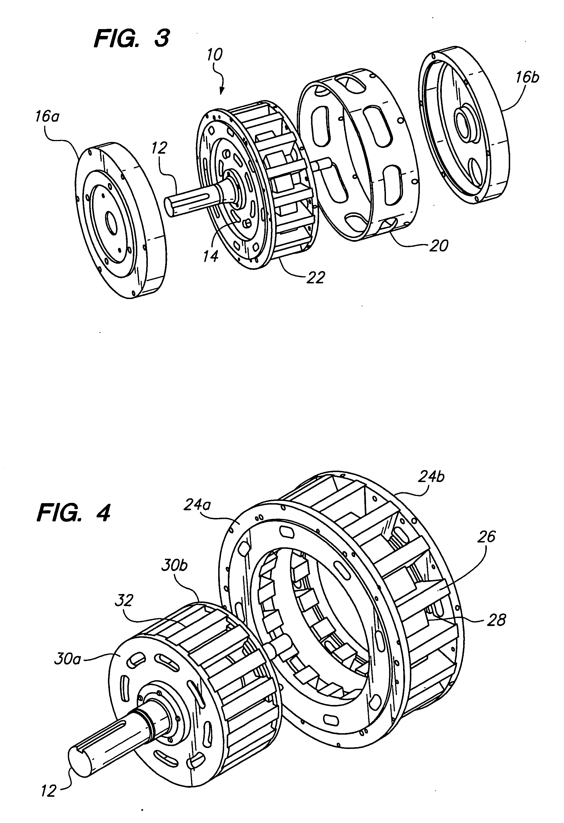
[0027] Referring now to the drawings wherein the showings are for purposes of illustrating preferred embodiments of the present invention only, and not for purposes of limiting the same, FIG. 1 is a perspective view of a toroidal motor 10 whereby the magnetic lines of flux generally follow a toroidal pattern. As used herein the term toroidal refers to a donut or torus shape. Referring to FIGS. 1-3, the motor 10 has a shaft 12 attached to and extending generally perpendicular from a rotor 14. The shaft 12 is supported within first and second end-bell housings 16a, 16b by respective bearings 18a, 18b. A motor housing 20 is disposed between the first and second end-bells 16a, 16b. As seen in FIG. 3, the motor also has a stator 22 which circumferentially surrounds the rotor 14.

[0028] Referring to FIGS. 1, 6 and 7, the stator 22 has two end-rings 24a and 24b that support a plurality of stator poles 26. The stator poles 26 are circumferentially disposed around the end-rings 24a, 24b. Each...

second embodiment

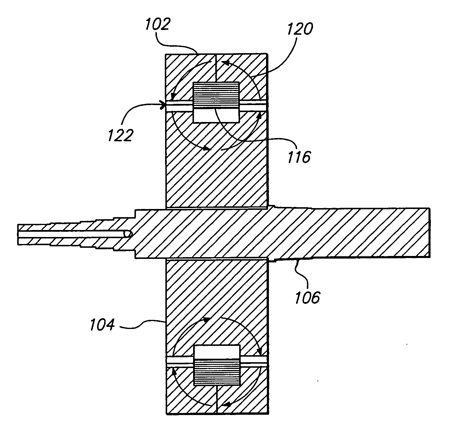
[0037] Referring to FIG. 10 the toroidal motor 100 is shown. The motor 100 has a generally circular stator 102 and rotor 104. A shaft 106 extends perpendicularly (i.e., axially) from the rotor 104. The rotor 104 is sized and configured to rotate within the stator 102. For the embodiment shown in FIG. 10, the motor 100 has sixteen rotor poles and sixteen stator poles. Because all of the poles are driven by a single coil, the number of stator poles is equal to the number of rotor poles so that all of the poles act in unison creating torque simultaneously. The stator 102 and rotor 104 is one phase of a complete motor. Three phases are needed in order to produce the necessary amount of starting torque.

[0038] Referring to FIG. 11, an exploded view of the rotor 104 and stator 102 with the shaft 106 removed is shown. The rotor 104 has rotor poles 108 spaced circumferentially around the exterior thereof. The rotor poles 108 are placed on the outside edges of the rotor 104 such that a groove...


PUM


Abstract

A toroidal motor having a generally circular rotor surrounded by an annular stator is disclosed. The rotor has a plurality of poles disposed about a circumference thereof. A shaft extends axially away from the poles and is attached to the rotor. The stator is generally annular and includes an annular winding surrounding the circumference thereof. Disposed about the winding are a plurality of stator poles. The number of stator poles is generally equal to the number of rotor poles. When the winding and hence the stator is excited, a magnetic field is produced between the stator and rotor poles that creates torque upon the shaft.

Description

BACKGROUND OF THE INVENTION [0001] 1. Field of the Invention [0002] The present invention generally relates to electrical motors and more particularly to an electric motor having a toroidal magnetic flux configuration to increase torque production. [0003] 2. Description of the Related Art [0004] Most typical electric motors or generators can be considered alternating current (AC) devices requiring alternating current at the basic operational level. For example, traditional direct current (DC) motors utilize mechanical switching mechanisms such as commutators and brushes to convert DC input current into AC current that operates the motor. A brushless DC motor is analogous to the traditional brush-type DC machine wherein the mechanical commutator has been replace by an electronic solid-state switching controller to create AC power from a DC source. The brushless DC motor typically has a 3-phase stator with a permanent magnet rotor such that it resembles an AC synchronous motor with an...

Claims


Application Information

Patent Timeline
Patent Type & Authority Applications(United States)
IPC IPC(8): H02K19/00H02K17/00H02K1/22
CPCH02K1/145H02K19/06
Inventor KERLIN, JACK H.
Owner PATENT
Why Eureka
Try Eureka