Organic light emitting diode circuit having voltage compensation function and method for compensating

a light-emitting diode and circuit technology, applied in static indicating devices, instruments, electroluminescent light sources, etc., can solve problems such as uneven stripe shape, reduced image quality, and dispersion, and achieve the effect of avoiding color differential in flat panel display and increasing the aperture ratio of the circui

Inactive Publication Date: 2006-04-20
INNOLUX CORP
View PDF5 Cites 69 Cited by
  • Summary
  • Abstract
  • Description
  • Claims
  • Application Information

AI Technical Summary

Benefits of technology

[0025] The present invention organic light emitting diode circuit equipped with the voltage compensation enables an OLED to be designed as a common cathode component such that the aperture ratio of the circuit can be increased. The present invention OLED that has the voltage compensation feature further allows array testing of the transistors in the circuit prior to the completion of the fabrication process for the circuit. Moreover, when circuits for voltage comparator unit, memory unit and data compensation unit are added to the OLED circuit, and an optoelectronic component is used as the control component, the brightness of the OLED can be adjusted based on the optoelectronic current value of the optoelectronic component such that the problem of color differential in the flat panel display can be avoided.

Problems solved by technology

In particular, active matrix (AM) OLED display devices are capable of high resolution (large number of pixels), high definition (fine pitch), and a large screen display, all of which are difficult for passive matrix (PM) type displays.
As a result, dispersion, not uniformity, in the electrical characteristics of the driver transistors across each of the pixels when the OLED elements do not emit light at a constant current, then dispersion will develop in the OLED element driver current of each of the pixels.
Dispersion in the brightness of light emitted by the OLED elements reduces the quality of the displayed image as a sandstorm state or carpet-like pattern unevenness is seen over an entire screen.
Stripe shape unevenness is also found, depending upon the manufacturing process.
One other disadvantage of the OLED 34 circuit is that the circuit cannot be designed as a common cathode component.
Thus, because of the varying current flow through the OLED, voltage measured at COM may also be irregular.
Consequently, when an OLED pixel circuit 10 is placed in an array of similar circuits to form an active-matrix LCD, varying voltages and current at COM make it difficult to provide a common ground to each of the pixel circuits located in the array.
One of the disadvantages in utilizing thin film transistors in an OLED pixel circuit is the long driving time required to drive the pixel circuit.
A long driving time can lead to threshold voltage swings in the transistors driving the pixel circuit.

Method used


Image

  • Organic light emitting diode circuit having voltage compensation function and method for compensating
  • Organic light emitting diode circuit having voltage compensation function and method for compensating
  • Organic light emitting diode circuit having voltage compensation function and method for compensating

Examples


third embodiment

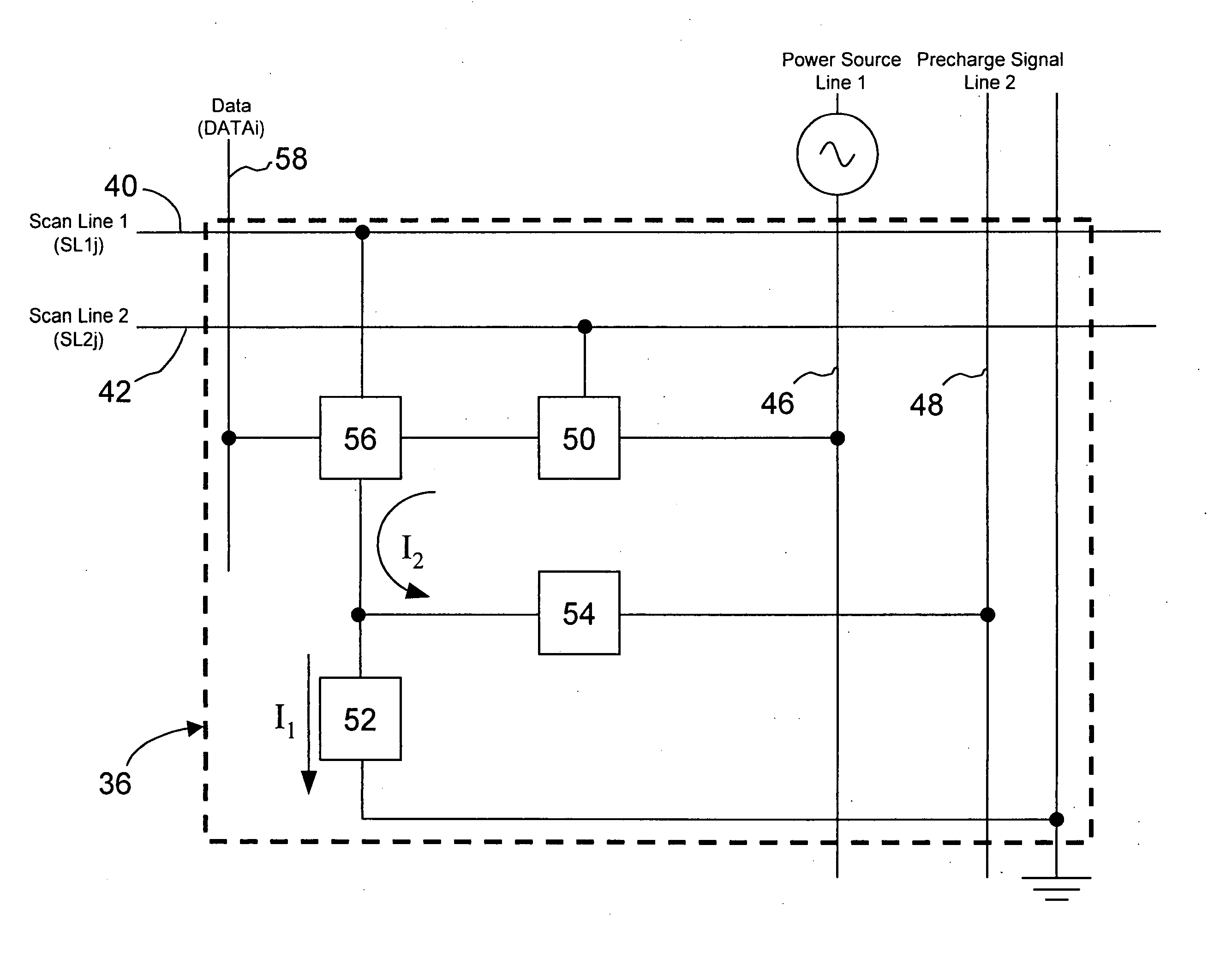
[0070] the present invention OLED that is equipped with a current control method and voltage compensation function is shown in FIGS. 4A-C, in a circuit diagram and timing sequence chart of pixel 80, respectively. As shown in FIG. 4A-B, the circuit consists of transistor 50, pixel control unit 84, OLED 52 and the control component 54. The only difference compared to that shown in FIG. 2 is the additional transistor 82 in the pixel control unit 84. The additional transistor 82 has a first terminal coupled to the gate terminal of transistor 62, a second terminal receiving a third scan line, and a third terminal coupled to ground.

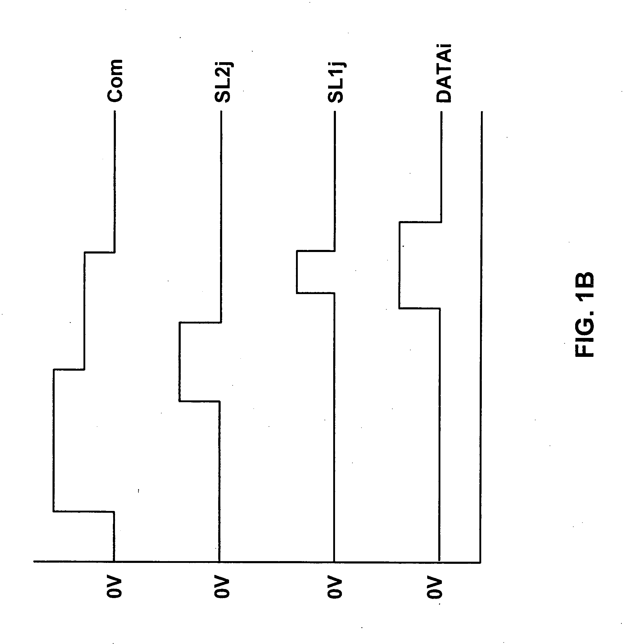
[0071] Referring now to FIG. 4C, wherein the operation mode of the third preferred embodiment is shown and is similar to that of FIG. 2B divided into a setting, data write-in at excitation phases. Similar to the timing sequence chart of FIG. 3C. During the setting phase, the third scan line is set to a high voltage potential to conduct through transistor 82, an...

first embodiment

[0072] A fourth preferred embodiment of the present invention wherein the OLED circuit allows both voltage compensation and color compensation as shown in FIGS. 5A-B. The circuit of the fourth preferred embodiment is similar to that of the first embodiment shown in FIG. 2 except that the precharge control component 54 is a optoelectronic component thin film transistor (TFT) 94. In addition, the circuit further includes a voltage comparator unit 88, a memory unit 90, and a data compensation unit 92.

[0073] The operation of the fourth preferred embodiment shown in FIGS. 5A-B can be described as follows. When the OLED 52 in the circuit is excited, the TFT 94 is exposed to visible light source and thus producing an auto electronic current. The magnitude of the optoelectronic current is dependent on the intensity of the visible light. When a flat display panel utilizing OLED is first exposed, the optoelectronic component TFT 94 is first exposed to an initial brightness of the OLED. The in...


PUM


Abstract

In organic emitting diode circuit that is equipped with voltage compensation function and a method for compensating voltage in the organic light emitting diode circuit are presented. The circuit includes a first transistor, a pixel control unit, a precharge control component and an OLED. The present invention OLED presents numerous benefits when compared to conventional OLED such as the present invention OLED can be designed as a common cathode component such that it has improved aperture ratio, it enables array testing of the circuit before the fabrication process is completed, and it allows color and brightness compensation in addition to voltage compensation.

Description

TECHNICAL FIELD [0001] The present invention generally relates to a light emitting device and circuits driving the light emitting device, and a method for operating the circuit and more particularly, relates to an organic light emitting diode circuit that incorporates voltage compensation function and a method for compensating the voltage of the circuit. BACKGROUND OF THE INVENTION [0002] Organic light emitting diodes (OLEDs) are typical light emitting elements currently seen as promising for all types of display devices. OLED display devices that use OLED elements as light emitting elements are thinner and lighter than existing liquid crystal display devices, and in addition, have characteristics such as high response speed suitable for dynamic image display, a wide angle of view, and low voltage drive. A wide variety of applications are therefore anticipated, from portable telephones and personal digital assistant (PDAs) to televisions, monitors, and the like. OLED display devices...

Claims


Application Information

Patent Timeline
Patent Type & Authority Applications(United States)
IPC IPC(8): G09G3/32G09G3/00H01L33/00H05B33/00
CPCG09G3/3233G09G2300/0465G09G2300/0819G09G2300/0842G09G2300/0861G09G2300/0866G09G2310/0251G09G2320/0285G09G2320/043G09G2360/148
Inventor GUO, HONG-RUYANG, CHEN-CHUNGTIEN, MING-CHUN
Owner INNOLUX CORP
Why Eureka
Try Eureka