Ophthalmic photography apparatus

a technology of ophthalmic photography and camera, which is applied in the field of ophthalmic photography apparatus, can solve the problems of large apparatus, increased cost, and inability to obtain good stereoscopic view, and achieve the effect of good image of the fundus for stereoscopic viewing

Inactive Publication Date: 2006-04-20
KOWA CO LTD
View PDF1 Cites 22 Cited by
  • Summary
  • Abstract
  • Description
  • Claims
  • Application Information

AI Technical Summary

Benefits of technology

[0016] The present invention has advantages in that the exit pupil position of the optical system that forms an image of the eye fundus on the image pickup means for use in stereoscopic photography is set to infinity, so the angle of incidence of rays to the deflecting optical element becomes constant, and the image for the left eye and the image for the right eye used for stereoscopic viewing are separated and caused to be incident upon the imaging device in alternating pixel columns, and thus the image for the left eye and the image for the right eye are not incident in superposition upon a single pixel column and thus a high-quality image for stereoscopic viewing can be obtained.
[0017] In addition, with the present invention, even when the focus is adjusted to compensate for differences in diopter of the eye being examined, the photographic stop disposed at a position conjugate to the anterior ocular segment is always positioned upon the object-side focal surface and the optical system is kept telecentric, so the phenomenon of a stereoscopic view that becomes more concave or convex the nearer to the periphery of the screen is eliminated. In addition, the optical element that guides the left and right images of the eye fundus for stereoscopic viewing to the stipulated pixel column is disposed in front of the image pickup means, and thus a good image of the fundus for stereoscopic viewing can be obtained without any crosstalk of the left and right eye fundus images upon the image pickup surface.

Problems solved by technology

However, with the conventional configuration as disclosed in any of Japanese Patent Nos. 2,642,417, 2,933,995 or 3,255,730, it is necessary to dispose lenses for each of the left-and-right pair of image-forming optical systems separately for the two optical paths, making the configuration complex and causing the apparatus to become large and also more costly, and moreover there are problems in that the adjustment of the optics of the left and right optical paths becomes exceedingly complex and time-consuming.
In addition, with the configuration disclosed in Japanese Laid Open Patent Publication No. 1998-165372, the two images from the two-aperture stop (the left image and the right image) are alternately incident upon the pixels of the imaging device, but there are problems in that both the left image and the right image are incident upon a single pixel in the periphery of the imaging surface, and thus a good stereoscopic view is not obtained, for example.
In addition, in stereoscopic photography of the eye fundus, the difference of diopter of the eye being examined must be taken into consideration, so if the focusing lens is moved from the reference position to compensate for the difference in diopter of the eye being examined, there are problems in that the conjugate relationship between the position of the anterior ocular segment and the two-aperture stop is upset and also the light passing through the respective apertures of the two-aperture stop is no longer guided to the pixels of the imaging device in a regular manner.
Moreover, even if a two-aperture stop is disposed upon the image-side focal surface of the focusing lens and upon the object-side focal surface of the imaging lens to thereby constitute an image-side telecentric optical system, the system is indeed image-side telecentric for the normal diopter (zero diopter) with an accurate stereoscopic view guaranteed, but if the diopter shifts toward the plus side or the minus side, there is a problem wherein the optical system cannot be kept telecentric during focus adjustment, resulting in a stereoscopic view that becomes more concave or convex the nearer to the periphery of the imaging surface.

Method used


Image

  • Ophthalmic photography apparatus
  • Ophthalmic photography apparatus
  • Ophthalmic photography apparatus

Examples


Embodiment Construction

[0037] The present invention is adapted for use in an ophthalmic photography apparatus able to take photographs for use in stereoscopic viewing. With reference to the following drawings, embodiments of the ophthalmic photography apparatus according to the present invention will now be described in detail based on a fundus camera.

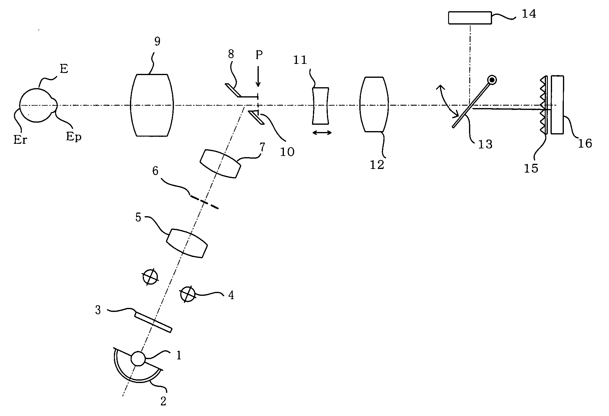
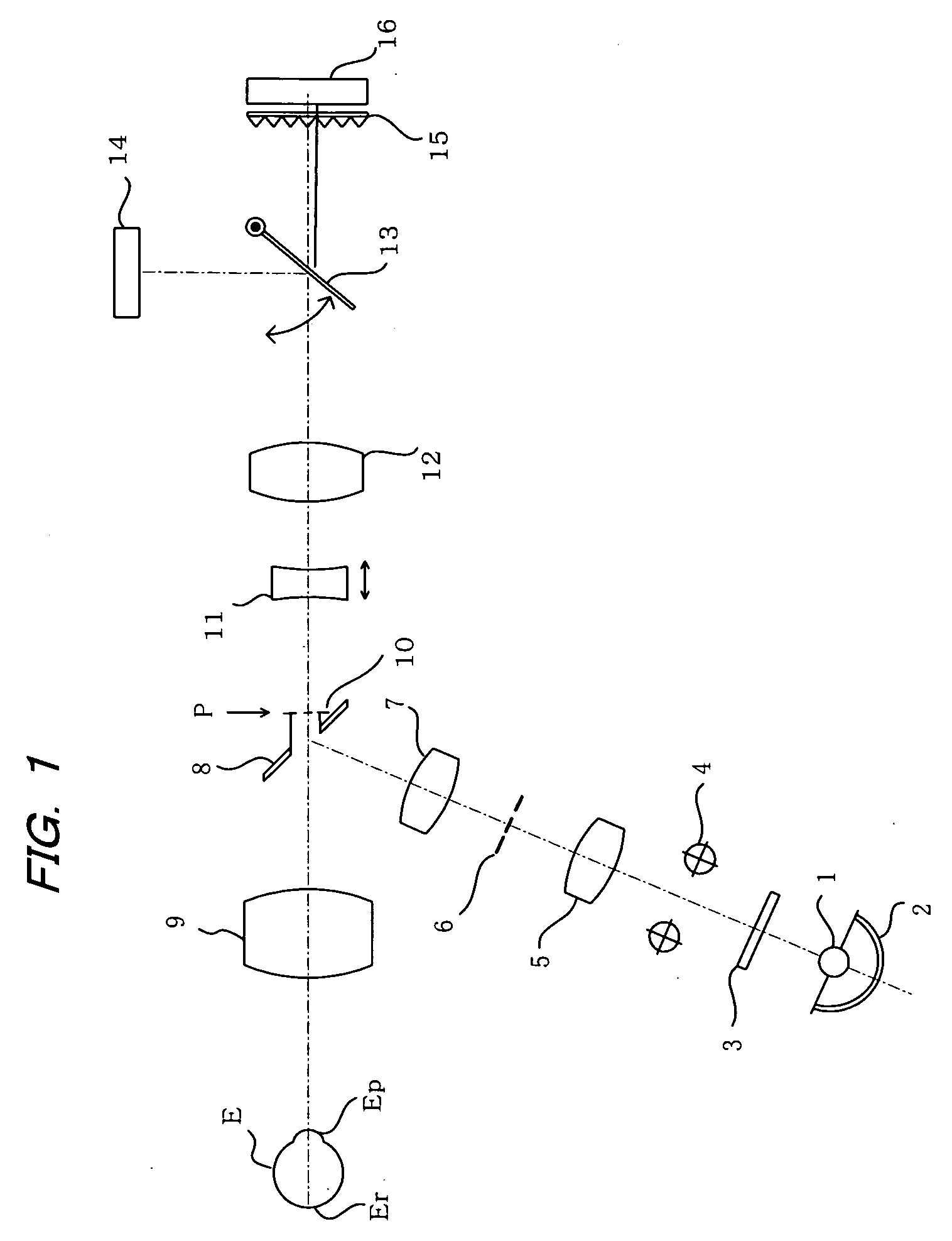
[0038]FIG. 1 illustrates a first embodiment of the present invention. The illustrated fundus camera comprises an illumination optical system that illuminates the fundus Er of an eye being examined E and a photographic optical system that photographs the eye fundus thus illuminated. In the illumination optical system, light emitted from a halogen lamp or other light source 1 and light reflected from a concave mirror 2 are passed through a visible-light-blocking and infrared-light passing filter 3 and the resulting infrared light is passed through a strobe 4 and a condenser lens 5 to illuminate a ring slit 6 disposed at a position conjugate to the anterior oc...


PUM


Abstract

A photographic stop with two apertures is disposed at a position substantially conjugate to the anterior ocular segment of the eye being examined and at a position on the object-side focal surface of an image-forming lens. An eye fundus image is guided via a lattice barrier disposed on the image-side focal surface of the image-forming lens to an imaging CCD. The photographic stop, image-forming lens, lattice barrier and CCD are moved as a unit for focus adjustment. With such a configuration, the photographic stop is always positioned upon the object-side focal surface of the image-forming lens with the optical system kept telecentric even when the focus is adjusted to compensate for differences in diopter of the eye. This eliminates the phenomenon of a stereoscopic view that becomes more concave or convex the nearer to the periphery of the screen and provides good images of the fundus for stereoscopic viewing without any crosstalk of the left and right fundus images upon the image pickup surface.

Description

BACKGROUND OF THE INVENTION [0001] 1. Field of the Invention [0002] The present invention relates to an ophthalmic photography apparatus, and more particularly to an ophthalmic photography apparatus that can simultaneously photograph both the left and right images required for stereoscopic viewing of the fundus of an eye being examined. [0003] 2. Description of the Prior Art [0004] With a conventional simultaneous stereoscopic fundus camera, as disclosed in Japanese Patent No. 2,642,417 and Japanese Patent No. 2,933,995, a two-aperture stop with two apertures (left and right) is provided at a position conjugate to the anterior ocular segment (conjugate to the pupil) of the eye being examined with respect to the objective lens, and each of the light beams from the fundus that pass through the two apertures is divided by a prism or the like into two optical paths, which are guided to a left-and-right pair of image-forming optical systems where separate images are formed in left and ri...

Claims


Application Information

Patent Timeline
Patent Type & Authority Applications(United States)
IPC IPC(8): A61B3/14A61B3/10
CPCA61B3/12A61B3/14
Inventor SUZUKI, TAKAYOSHI
Owner KOWA CO LTD
Why Eureka
Try Eureka