Light guide plate and method for fabricating the same

a technology of light guide plate and microstructure, which is applied in the direction of planar/plate-like light guide, lighting and heating apparatus, instruments, etc., can solve the problems of difficult to fabricate a complex microstructure for light dispersion, difficult to achieve arc shape, inconsistent light output uniformity of light guide plate, etc., and achieve uniform light dispersion

Inactive Publication Date: 2006-04-20
IND TECH RES INST
View PDF16 Cites 76 Cited by
  • Summary
  • Abstract
  • Description
  • Claims
  • Application Information

AI Technical Summary

Benefits of technology

[0015] In light of the above prior-art drawbacks, a primary objective of the present invention is to provide a light guide plate and a method for fabricating the same, so as to achieve a light guidance and uniform light dispersion effect.

Problems solved by technology

On the contrary, if the LED is used as the backlight source for the light guide plate, the light guide plate having the V-shaped notch on the bottom thereof will have an obviously bright band image appeared at the beginning of LED light emission and along the direction of the light emission, such that the light output uniformity of the light guide plate is very inconsistent.
The light incidence microstructure fabricated using such method, however, requires fabrication of two molds, so as to require a relatively higher cost.
Moreover, it is impossible to fabricate a complex microstructure for light dispersion, such as an arc shape or an irregular curved design, if the microstructure is fabricated on the mold using a mechanical processing method.
Therefore, when the mechanical processing method is employed to directly fabricate the microstructure on the light guide plate, shapes or dimensions of the microstructure are both limited.
Theoretically, such prior-art technique is not able to achieve a design which provides a better light dispersion effect.
However, fabrication of the prism is difficult and such technique thus does not allow fast mass production and requires a relatively higher cost.
The design of light incidence curved surfaces described in the U.S. Pat. No. 6,568,822 B2 is of a non-spherical curvature and thus does not allow mass production in actual situations.
Therefore, the technique disclosed in such patent neither allows mass production nor reduces a cost due to complicated fabrication.
However, referring to U.S. Pat. No. 6,139,163, the light beam emitted from the light source needs to be reflected and refracted for a number of times before entering into the interior of the light guide plate, such that light energy is dramatically lost and a light output is reduced as a result.
Additionally, the structure of the light guide plate disclosed by such patent is very complex and might not be produced in actual situations, and therefore might not comply with economic efficiency.

Method used


Image

  • Light guide plate and method for fabricating the same
  • Light guide plate and method for fabricating the same
  • Light guide plate and method for fabricating the same

Examples


first embodiment

The First Embodiment

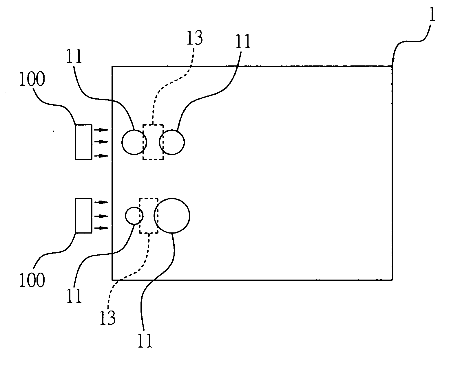
[0051]FIG. 1 through to FIG. 2E are schematic diagrams showing a light guide plate and its fabricating method according to the first embodiment of the present invention. Referring to FIG. 1, a light guide plate 1 is provided with a plurality of arc-shaped first opening portions 11.

[0052] In the present embodiment, the light guide plate 1 may be made of a transparent acrylic sheet with a preferred refraction index. Four arc-shaped first opening portions 11 are provided on edges of the light guide plate 1 at positions corresponding to a light source 100 which can be a light emitting diode (LED). Each of the arc-shaped first opening portions 11 can be a circle structure, and a concave lens 13 is formed between two of the adjacent first opening portions 11. Each of the first opening portions 11 can be a hole or a recessed cavity, and dimensions and distances between the first opening portions 11 can be varied from each other as shown in FIG. 1.

[0053] Furthermore, t...

second embodiment

The Second Embodiment

[0065]FIG. 3A and FIG. 4A through to FIG. 4F are schematic diagrams showing the light guide plate and method for fabricating the same according to the second embodiment of the present invention. In order to provide a clearer description for the present invention, elements in this embodiment consistent or similar to that in the first embodiment are illustrated using the same or similar reference numerals and their details are not further described.

[0066] As illustrated in FIG. 3A, the second embodiment differs from the first embodiment in that a plurality of arc-shaped second opening portions 15 is formed on an edge of the light guide plate 1 at positions corresponding to the light source 100, and each of the first opening portions 11 has a size different from each other.

[0067] Therefore, each of the concave lens 13 can be formed on the edge of the light guide plate 1, such that a propagated light source of the light source 100 is uniformly dispersed to differe...

third embodiment

The Third Embodiment

[0076]FIG. 3B through to FIG. 3E are schematic diagrams showing modifications of the foregoing embodiments. The elements similar to those described in the foregoing embodiment are illustrated by the same or similar reference numerals and not further described in details, except for the modifications to further define the technical feature of the present invention.

[0077] Referring to FIG. 3B, the circular hole of the first opening portion 11 shown in the second embodiment is modified to be an elliptical hole or recessed cavity. In the light guide plate 1 in the present embodiment, curvature values of two curved surfaces of the first opening portion 11 having an elliptical shape can be determined by the angle of the light source divergence desired. The curvature value of each of the two curved surfaces of the first opening portion 11 can differ from each other. Further, the size and distance between the first opening portions 11 can be different from each other.

[...


PUM


Abstract

A light guide plate and method for fabricating the same are proposed. An injection molding process is performed to form at least an arc-shaped first opening portion on the light guide plate, so that a concave lens structure is formed on an edge of the first opening portion to be in line with a light source. By such arrangement, the concave lens structure can direct light and achieve a uniform light dispersion effect.

Description

FIELD OF THE INVENTION [0001] The present invention relates to a light guide plate and a method for fabricating the same, and more particularly, to a light guide plate and a method for fabricating the same applicable to a backlight module. BACKGROUND OF THE INVENTION [0002] Along with the booming development of a light source such as a light emitting diode (LED) which has been massively used as a backlight source in car lights, advertising light boxes and light guide plates, the LED light source has been identified as a trend for the future development of illumination. Referring to the dramatic growth of applications of a LED light source in a backlight module, in order to meet the requirement of environmental protection and miniaturization for the backlight source of the backlight module, it is desirable to replace a line source, a cold-cathode fluorescent tube (CCFT) source, with a discrete or point-like source such as the LED. [0003] The backlight module mainly comprises a light ...

Claims


Application Information

Patent Timeline
Patent Type & Authority Applications(United States)
IPC IPC(8): F21V7/04
CPCG02B6/0016G02B6/002G02B6/0036G02B6/0055G02B6/0065
Inventor SUN, YI-TINGLAI, HWA-TANGYAO, PO-HUNGPAO, YU-NAN
Owner IND TECH RES INST
Why Eureka
Try Eureka