Multi-speed motor system combining at least a one speed electric motor, series resistor and power switches

a multi-speed motor and series resistor technology, applied in the field of motors, can solve the problems of reducing limiting the operation to two or maximum three speed, and the complexity and cost of such controllers are significantly higher than the lower cost two or three, so as to reduce the speed of the motor and the effect of electrical input power

Inactive Publication Date: 2006-04-20
BROSE FAHRZEUGTEILE GMBH & CO KG HALLSTADT (DE)
View PDF23 Cites 13 Cited by
  • Summary
  • Abstract
  • Description
  • Claims
  • Application Information

AI Technical Summary

Problems solved by technology

However, most of these solutions, which are more economically feasible, are limited to two or maximum three speed operations.
However, the complexity and cost of such controllers are significantly higher than the lower cost two or three speed conventional solutions.

Method used


Image

  • Multi-speed motor system combining at least a one speed electric motor, series resistor and power switches
  • Multi-speed motor system combining at least a one speed electric motor, series resistor and power switches
  • Multi-speed motor system combining at least a one speed electric motor, series resistor and power switches

Examples


Embodiment Construction

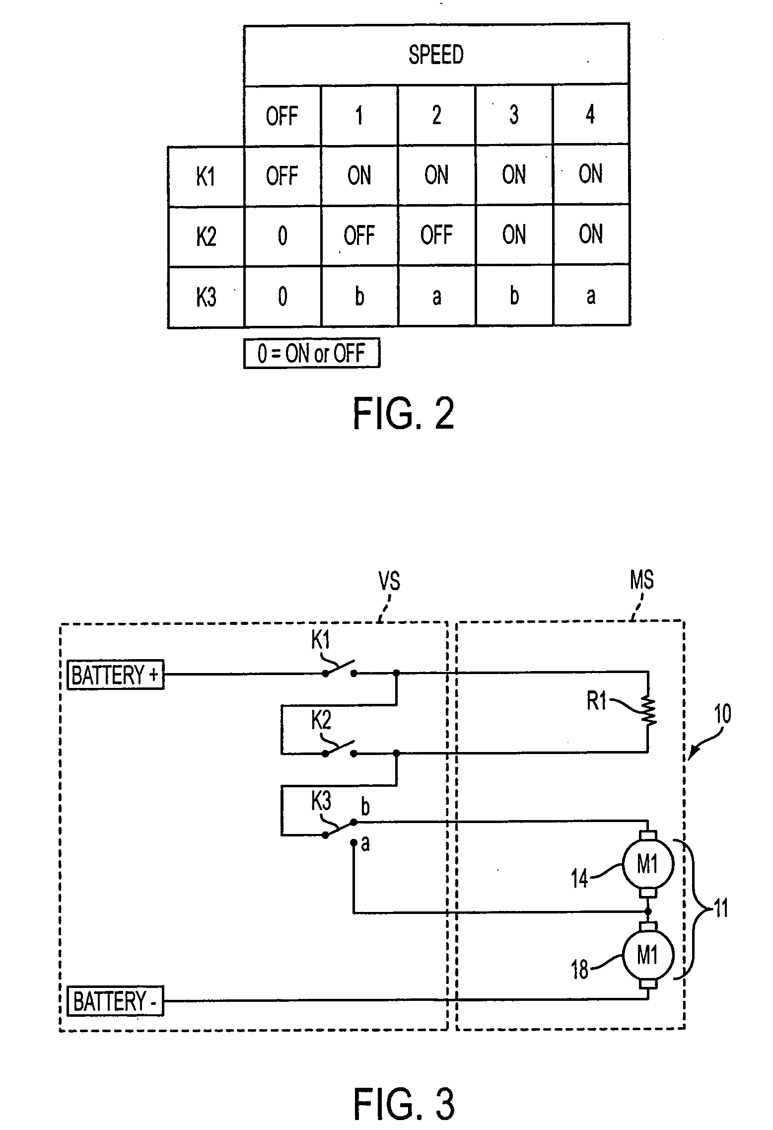
[0024] The embodiment combines two of the available technologies for speed control mentioned above and develops a new method and system for four-speed operation. More specifically, by systematically switching and energizing a two-speed motor (dual armature winding with dual commutator system) combined with a current limiting device through a switch structure described below, four distinctive operating speeds can be accomplished.

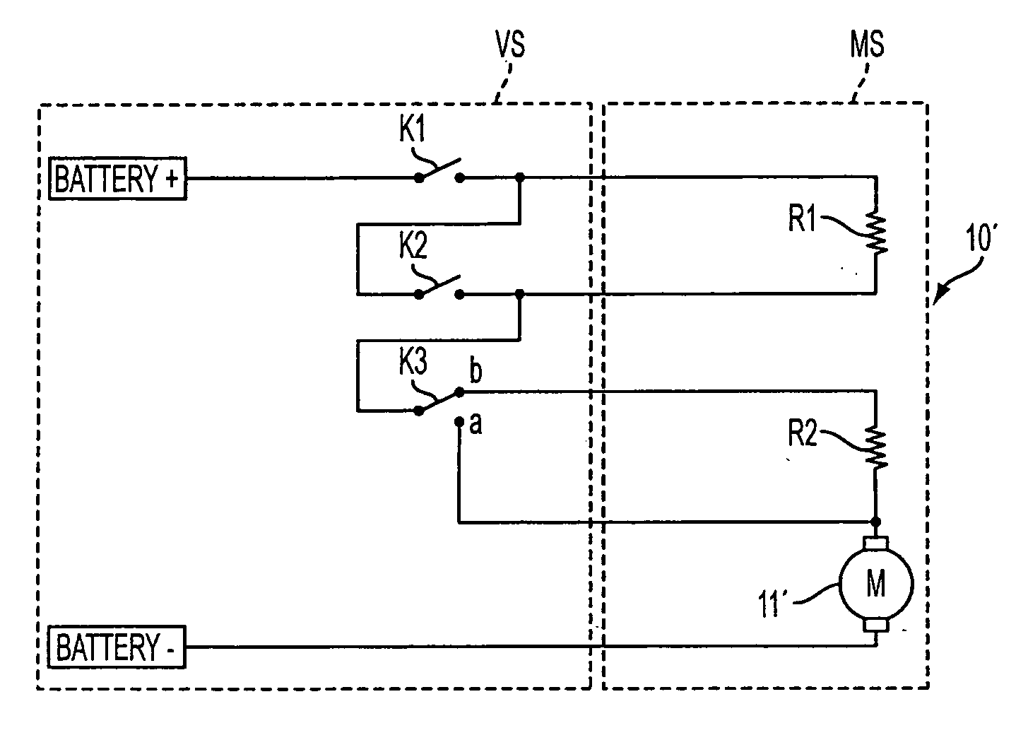
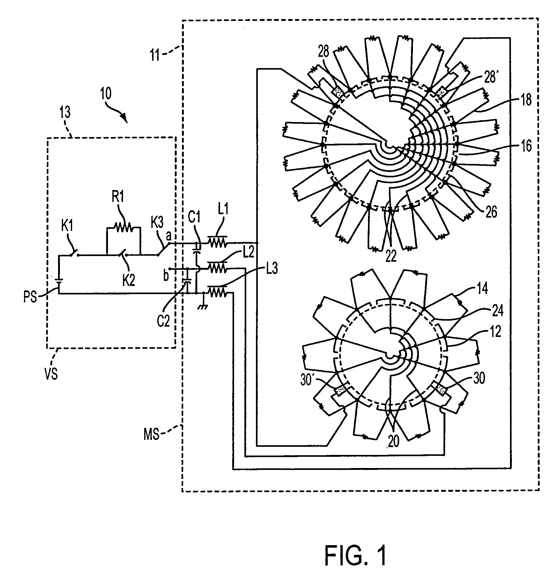
[0025] A system, provided in accordance with the principles of the invention is shown, generally indicated at 10, in FIG. 1. The system 10 includes a motor 11 and vehicle side circuitry 13. The motor 11 is described in the provisional patent applications 60 / 560,457, filed on Apr. 8, 2004, and 60 / 579,949, filed on Jun. 15, 2004, the contents of which are hereby incorporated by reference into the present specification.

[0026] As shown in FIG. 1, a two speed motor 11 has a link wound, low speed (LS) commutator 12 electrically connected with a LS winding 14, and...


PUM


Abstract

A multi-speed permanent magnet D.C. electric motor system 10 includes at least one permanent magnet DC electric motor 11 configured to operate at at least one speed. A current limiting device R1 is constructed and arranged to lower electrical input power to the motor 11 so that a speed of the motor is reduced, when the motor is powered together with the current limiting device, as compared to a speed of the motor powered absent the current limiting device. Switching structure K1, K2, K3 is associated with the current limiting device to selectively operate the motor at at least three discrete speeds, even though the motor is configured for at least one-speed operation.

Description

[0001] This application is based on Provisional Application No. 60 / 619,995 filed on Oct. 19, 2004 and claims the benefit thereof for priority purposes.FIELD OF THE INVENTION [0002] This invention relates to motors for automotive applications such as, but is not limited to, engine cooling, HVAC (Heating, Ventilation, and Air Conditioning), or ABS (Anti-lock Braking System). BACKGROUND OF THE INVENTION [0003] There is an increasing demand of multi-speed operation of electric motors used in automotive applications, especially in engine cooling applications where lower fan speed operation is required to reduce power consumption and the noise pollution during lower or normal engine load conditions. The high fan speed from the engine cooling unit is required for maximum, worst case engine load conditions. There are a variety of different configurations and methods available on the market for two or multi speed operation of electric motors. [0004] For Permanent Magnet Direct Current Brush ...

Claims


Application Information

Patent Timeline
Patent Type & Authority Applications(United States)
IPC IPC(8): H02P3/08
CPCH02P7/08H02P5/68
Inventor SIMOFI-ILYES, ATTILALAKERDAS, ANDREWTONER, MIKE
Owner BROSE FAHRZEUGTEILE GMBH & CO KG HALLSTADT (DE)
Why Eureka
Try Eureka