Dental implant

Inactive Publication Date: 2006-04-20
Z SYST SCHWEIZ
View PDF10 Cites 21 Cited by
  • Summary
  • Abstract
  • Description
  • Claims
  • Application Information

AI Technical Summary

Benefits of technology

[0011] In a particularly preferred embodiment of the invention, the pin has a conical part, in particular over a considerable extent, for example greater than 50% of its length. This has the advantage that a crown can more easily be anchored in a stable manner onto a stump by a clamping effect when the crown is pushed onto the cone. This is especially the case when the pin tapers conically starting from the intermediate section and, for example, only at an end area does the pin have a structure permitting engagement of an insertion screwing instrument. Advantageously, only a small portion of the end area of the pin is designed as a hexagon. However, a great many other structures are possible at the end of the pin, for example negative slit or cross structures.
[0012] A conical or tapering portion of the pin has a further important advantage. Generally, the shapes for crowns and bridges are obtained by taking an impression of a prepared tooth stump or of an implant from the patient. The impression that has been taken is used to create a plaster model from which a matching dental crown or bridge is produced. In a more recent method, an impression is likewise taken from the patient. However, this is then followed by laser scanning in order to determine the correct fit. A dental crown or bridge is then milled directly using the data obtained from this laser scanning. This procedure is referred to in dentistry as a CAD/CAM procedure. CAD stands for computer-aided design, and CAM for computer-aided manufacturing. In this procedure, it has to be borne in mind that not all shapes of bridges and crowns can be produced using current milling machines. In the case of a pin which is at least substantially conical, the corresponding cavity in a crown or bridge is likewise conical. In the CAD/CAM procedure, such a shape can be safely produced in particular for an inclination angle of the flanks of 4° and greater.
[0013] Moreover, it is particularly advantageous if a transition into the pin, in particular starting from the intermediate section, is realized in the form of a rounded corner. By avoiding sharply edged transitions it is possible, on the one hand, to avoid a notch effect during loading, with the

Problems solved by technology

However, a disadvantage of glass ceramic is the s

Method used


Image

  • Dental implant
  • Dental implant

Examples


Embodiment Construction

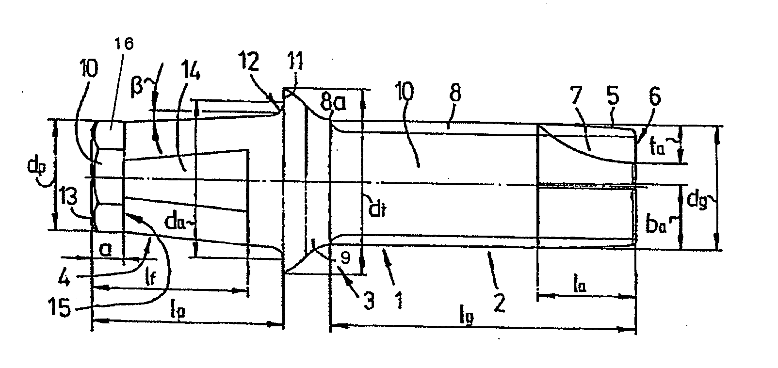
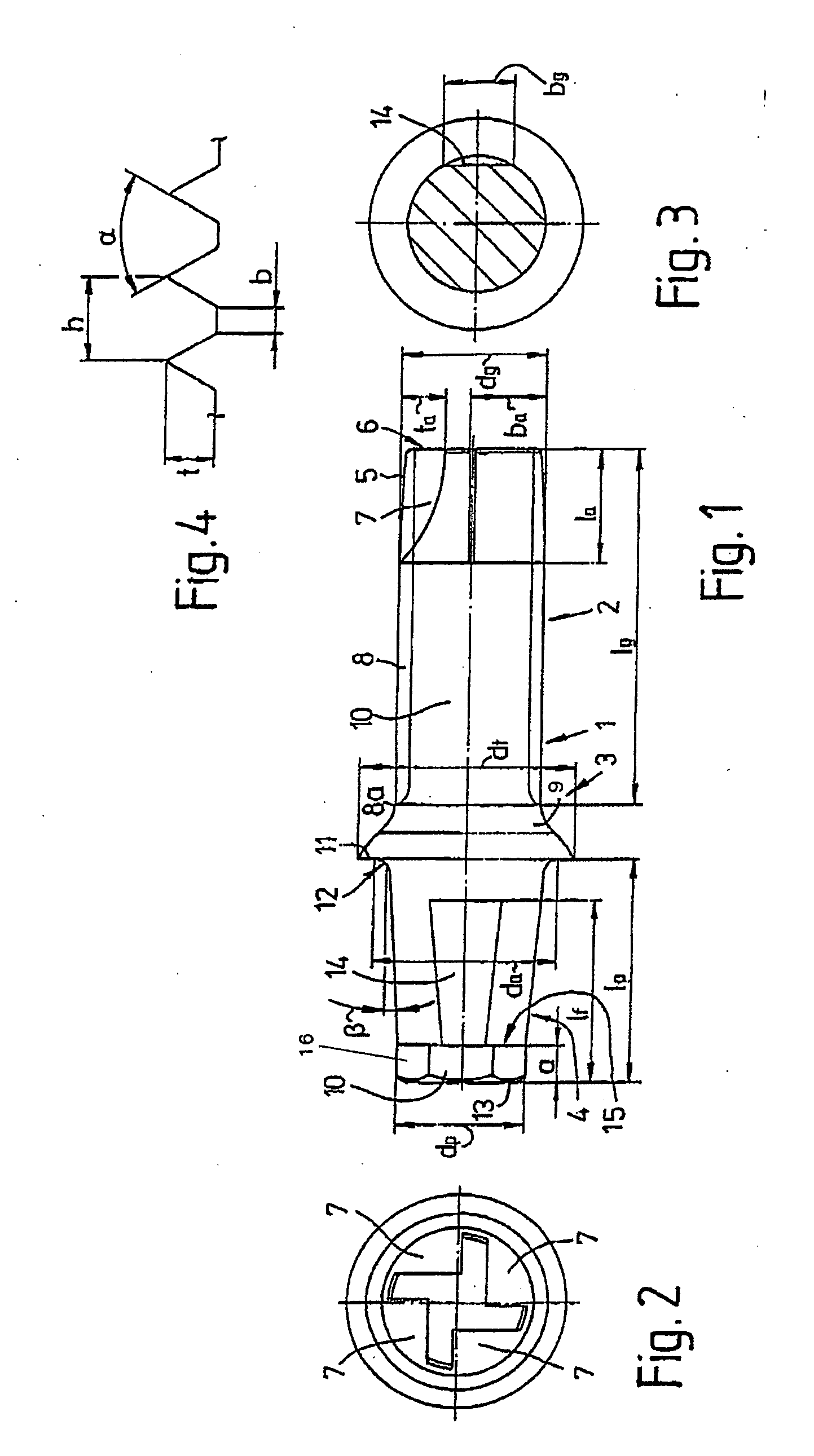
[0021] In FIGS. 1 to 4, a dental implant 1 is shown which comprises a threaded section 2, an intermediate section 3 and a pin 4. The threaded section 2, the intermediate section 3 and the pin 4 are positioned concentrically with respect to one another and are substantially rotationally symmetrical. The threaded section has a length lg which is 10 mm here, by way of example. The threaded section tapers in the front area 5 so as to facilitate the insertion operation during implantation.

[0022]FIG. 4 shows an enlarged representation of the geometry of a preferred thread 8 in the non-tapering area. This thread is a right-hand cutting thread profile with, for example, a thread height h of 0.6 mm. The thread depth t is 0.34 mm, and the flank angle α is 60°. The thread 8 is configured as a trapezoid thread, with a thread width b of 0.18 mm at its foot.

[0023] In the front area 5, reaching as far as the end 6 of the threaded section 2, deepening recesses 7 (see also FIG. 2) are provided in ...


PUM


Abstract

A dental implant including a one-piece base body having a threaded section and a pin on which a dental crown can be mounted. The one-piece base body is made from zirconium oxide or a mixture of zirconium oxide and aluminum oxide.

Description

CROSS REFERENCE TO RELATED APPLICATIONS [0001] This application is a continuation of International Application No. PCT / DE2004 / 000868, having an international filing date of Apr. 26, 2004, which designated the United States, and claims the benefit under 35 USC §119(a)-(d) of German Application No. 103 19 036.8, filed Apr. 25, 2003, the entireties of which are incorporated herein by reference.FIELD OF THE INVENTION [0002] The invention relates to a dental implant including a one-piece body having a threaded section and a pin on which a dental crown can be mounted. The one-piece base body is made from zirconium oxide or a mixture of zirconium oxide and aluminium oxide. BACKGROUND OF THE INVENTION [0003] Dental implants are used as tooth root replacements after loss of teeth, for example for receiving solidly cemented dental crowns and bridges and also superstructures for anchoring of removable dental prostheses. [0004] A dental implant made of glass ceramic and used for replacement of ...

Claims


Application Information

Patent Timeline
IPC IPC(8): A61C8/00
CPCA61C8/0012A61C8/005A61C8/0066A61C8/0075A61C8/00A61C13/00
Inventor VOLZ, ULRICH
Owner Z SYST SCHWEIZ
Why Eureka
Try Eureka