Intraocular lens inserter

a technology of inserters and lenses, applied in the field of ophthalmic surgical devices for implanting lenses, can solve the problems of deteriorating vision, affecting the ophthalmic effect of patients, and acclimating to the thick lenses required in glasses, and achieves the effects of preventing buckling of the advancer, reducing the risk of eye damage, and being easy to bend

Inactive Publication Date: 2006-04-20
DUSEK VACLAV +1
View PDF23 Cites 136 Cited by
  • Summary
  • Abstract
  • Description
  • Claims
  • Application Information

AI Technical Summary

Benefits of technology

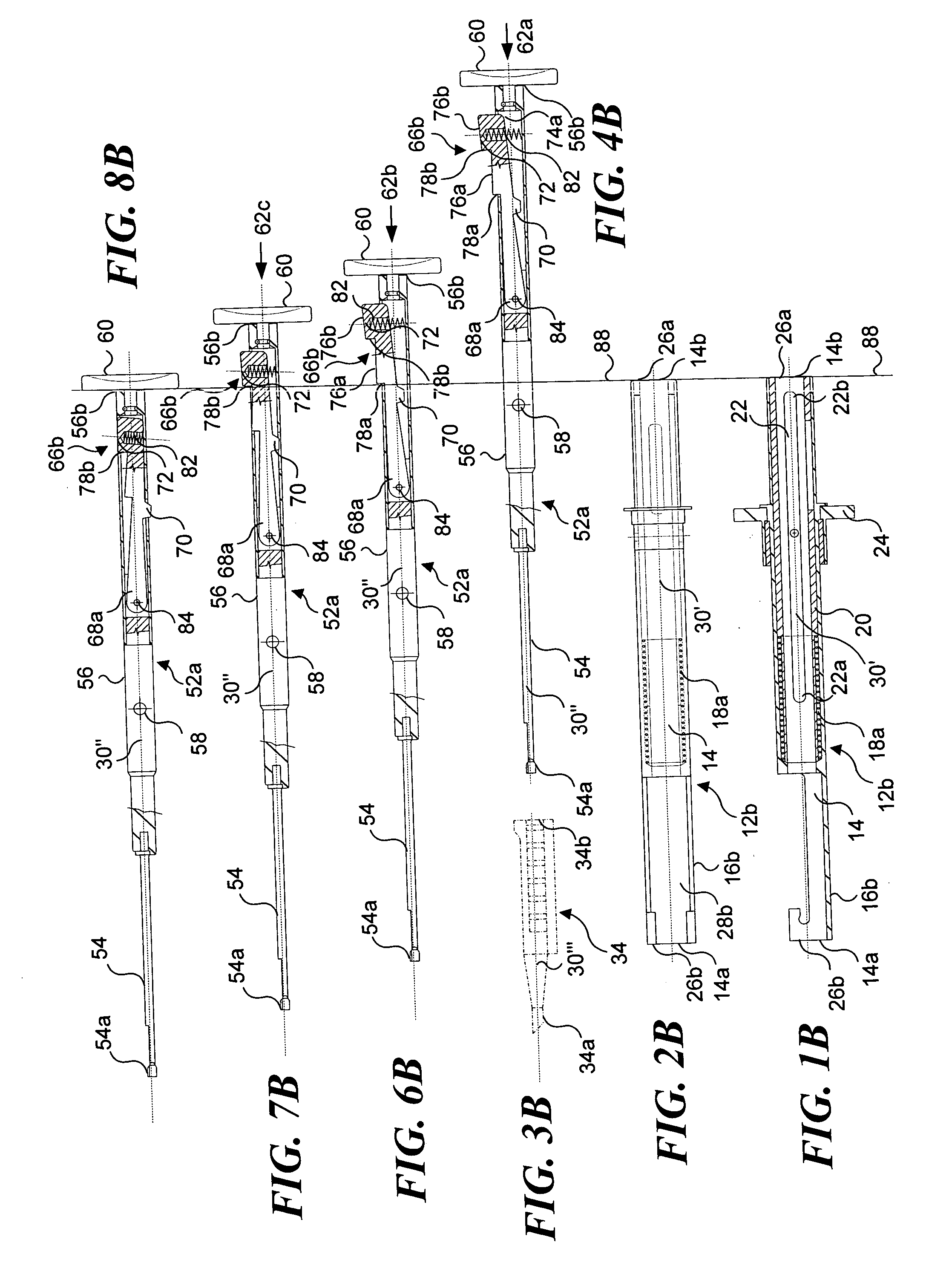
[0028] The mover also includes a plunger at its proximal end and an advancer at its distal end. The advancer is sufficiently flexible so that the advancer readily bends when passing from the handle portion and into the cartridge receiver portion while the cartridge receiver portion is pivoted to an acute angle relative to the handle portion. In one embodiment, a bore reducer is disposed in the internal bore of the handle portion. The bore reducer prevents buckling of the advancer within the handle portion, by confining the advancer to minimize its transverse deflection relative to the longitudinal axis of the handle portion. The intraocular lens inserter preferably includes a surface area disposed at the proximal end of the plunger. The surface area is disposed such that pressure applied thereto is directed along the longitudinal axis to advance the plunger along the longitudinal axis of the handle portion.

Problems solved by technology

Cataracts cause vision to deteriorate, because the clouding of the lens diffuses light and thus, prevents the light from being focused on the retina, which is required to produce sharp images.
Patients were given glasses to wear after this surgery, and they often encountered problems acclimating to the thick lenses required in the glasses.
However, the surgeon cannot readily control the rate at which the lens is ejected from the load chamber and into the eye.
Thus, a large diopter lens will exhibit a significant friction as it is advanced, and when a surgeon begins to push the IOL out of the load chamber, the surgeon may overshoot the point where the IOL starts to open, because of the sudden release of stored, elastic energy in the IOL.
Furthermore, the surgeon does not have the option of rotating a distal portion of the apparatus in order to provide a more comfortable position for the surgeon's hand to utilize the apparatus and thus, provide better control of positioning the IOL through the small incision.
Although this helical screw assembly provides the surgeon with better control, turning the push rod takes more time and there is no visual indication of the disposition of the IOL in the inserter prior to its ejection from the inserter.
However, opening the forceps tips to a position wider than the incision in the eye exposes the patient to a greater risk of injury to the eye if the forceps tips contact delicate parts of the eye.
Also, the device is not versatile in that it fails to accommodate commonly used lens injector cartridges by instead utilizing the sling.

Method used


Image

  • Intraocular lens inserter
  • Intraocular lens inserter
  • Intraocular lens inserter

Examples


sixth embodiment

[0135] an inserter, shows a fourth configuration of a multi-step detent, multi-step detent 66d, which is disposed in a first cavity 74b, as illustrated in FIGS. 14A, 14B, and 14C. With reference to FIG. 14A, multi-step detent 66d includes first detent releaser 100a, and a second detent releaser 100b. These releasers are disposed under an arm 98b that is mounted to the outer surface of the elongate housing. This elongate housing includes a first orifice 96b and a second orifice 96c that are spaced apart along longitudinal axis 30′ at positions defining the first detent position and the second detent position. The first detent releaser is adjacent to the first orifice, and the second detent releaser is adjacent to the second orifice. A mover 52d also includes first cavity 74b and a pin 94c. Pin 94c is disposed within the first cavity and is biased outwardly by a cantilevered spring arm 102. The pin is sized to fit within the first orifice and the second orifice. FIGS. 14A, 14B, and 14...

seventh embodiment

[0139] an inserter includes a fifth configuration of a multi-step detent, multi-step detent 66e, as shown in FIGS. 15A, 15B, and 15C. Multi-step detent 66e includes a collar 104 that is disposed adjacent to an orifice 96d formed in the housing. Collar 104 includes a pin 94d, and the collar is biased to force the pin inwardly through the orifice by a helical-type collar spring 106. Collar spring 106 is disposed between the exterior surface of the elongate housing and the radially inner surface of the collar, at a point opposite pin 94d. A mover 52e also includes first cavity 74a and a second cavity 90c, which are each sized to receive pin 94d, when it passes through orifice 96d. FIG. 15A illustrates a portion of intraocular lens inserter 10 prior to engagement of multi-step detent 66e in the first detent position. In this Figure, collar spring 106 is shown in a compressed state such that pin 94d is biased inwardly, pushing on mover 52e.

[0140] When the surgeon applies longitudinal ma...


PUM


Abstract

An intraocular lens (IOL) inserter and method of use ensure that an artificial intraocular lens is controllably ejected from a cartridge and into a patient's eye by using successive, predefined detent positions. One embodiment has a distal pivotal portion that can be pivoted to a desired angle as a mover advances the IOL into the eye. A detent controls the motion of the mover. In one embodiment, the detent includes a longitudinally extending component with a plurality of stair steps, so that a face of each stair step engages the housing at each different predefined detent position. Other embodiments include at least one orifice in the housing, so that when the orifice is aligned with a pin or protrusion, it engages the orifice to define a detent step. Another embodiment includes a spring-loaded collar that biases a pin into a predefined detent step.

Description

RELATED APPLICATIONS [0001] This application is a continuation-in-part of a copending patent application Ser. No. 10 / 971,630, filed on Oct. 20, 2004, the benefit of the filing date of which is hereby claimed under 35 U.S.C. § 120.FIELD OF THE INVENTION [0002] The present invention generally relates to a method and ophthalmic surgical devices for implanting lenses, and more specifically, to apparatus and a method for controlling advancement of the intraocular lens from a cartridge and into the eye, so that a lens is advanced through successive, defined steps, which are selected by depressing a detent. BACKGROUND OF THE INVENTION [0003] A cataract is a clouding of the normally clear, natural internal lens of the eye. Cataracts cause vision to deteriorate, because the clouding of the lens diffuses light and thus, prevents the light from being focused on the retina, which is required to produce sharp images. This condition is most commonly caused by the natural aging process that causes...

Claims


Application Information

Patent Timeline
Patent Type & Authority Applications(United States)
IPC IPC(8): A61F9/00
CPCA61F2/1664
Inventor DUSEK, VACLAVDUSEK, JARMILA
Owner DUSEK VACLAV
Why Eureka
Try Eureka