Posterior spinal arthroplasty-development of a new posteriorly inserted artificial disc and an artificial facet joint

Inactive Publication Date: 2006-04-20
DISC MOTION TECH
View PDF99 Cites 151 Cited by
  • Summary
  • Abstract
  • Description
  • Claims
  • Application Information

AI Technical Summary

Benefits of technology

[0057] Thus, the present invention overcomes the problems and disadvantages associated with current disc replacement strategies. It has all the benefits associated with posterior lumbar inter-body fusion surgery, but at the same time it allows movement at that leve

Problems solved by technology

The facet joint is in fact a synovial joint and suffers from the problems that are known to affect other synovial joints in the body like the hip and the knee.
Anterior inter-body fusion on its own is still questioned because it does not provide a posterior tension band.
One of the disadvantages of anterior lumbar arthroplasty is that the facet joints at this level continue to move and also continue to act as a pain generator.
The other disadvantage of anterior lumbar arthroplasty is that the majority of spine surgeons are not familiar with the anterior approach, and althoug

Method used


Image

  • Posterior spinal arthroplasty-development of a new posteriorly inserted artificial disc and an artificial facet joint
  • Posterior spinal arthroplasty-development of a new posteriorly inserted artificial disc and an artificial facet joint
  • Posterior spinal arthroplasty-development of a new posteriorly inserted artificial disc and an artificial facet joint

Examples


Embodiment Construction

Lumbar Disc Prosthesis

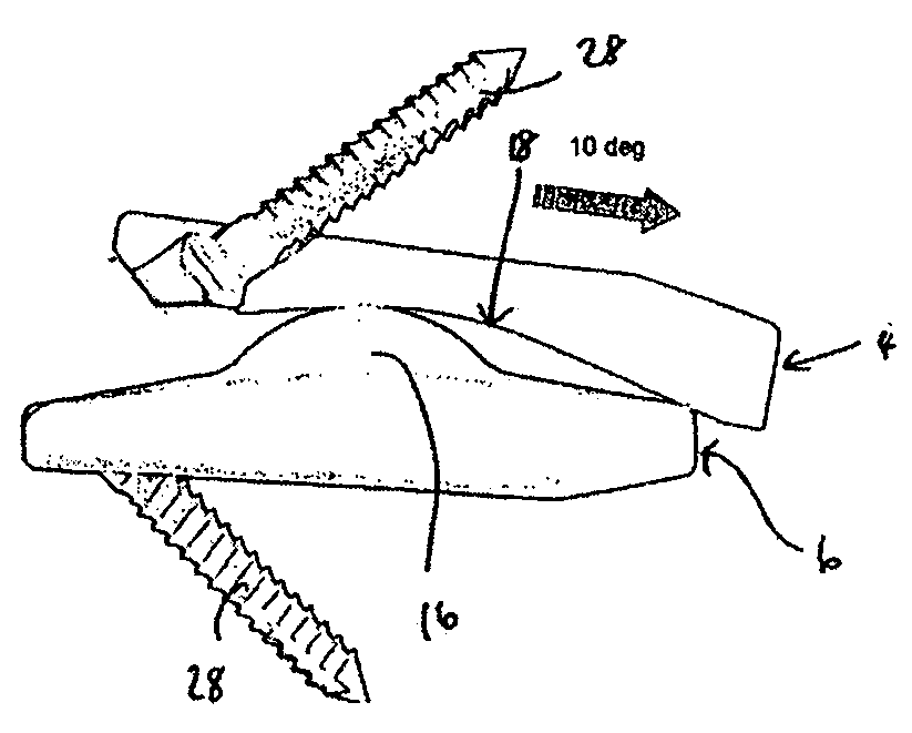
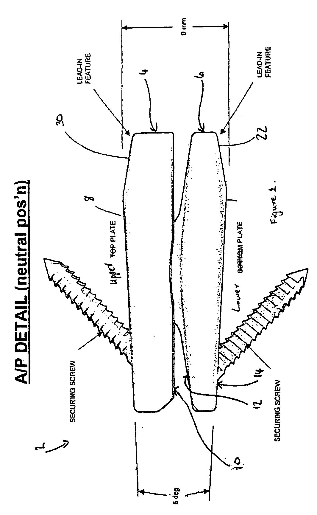
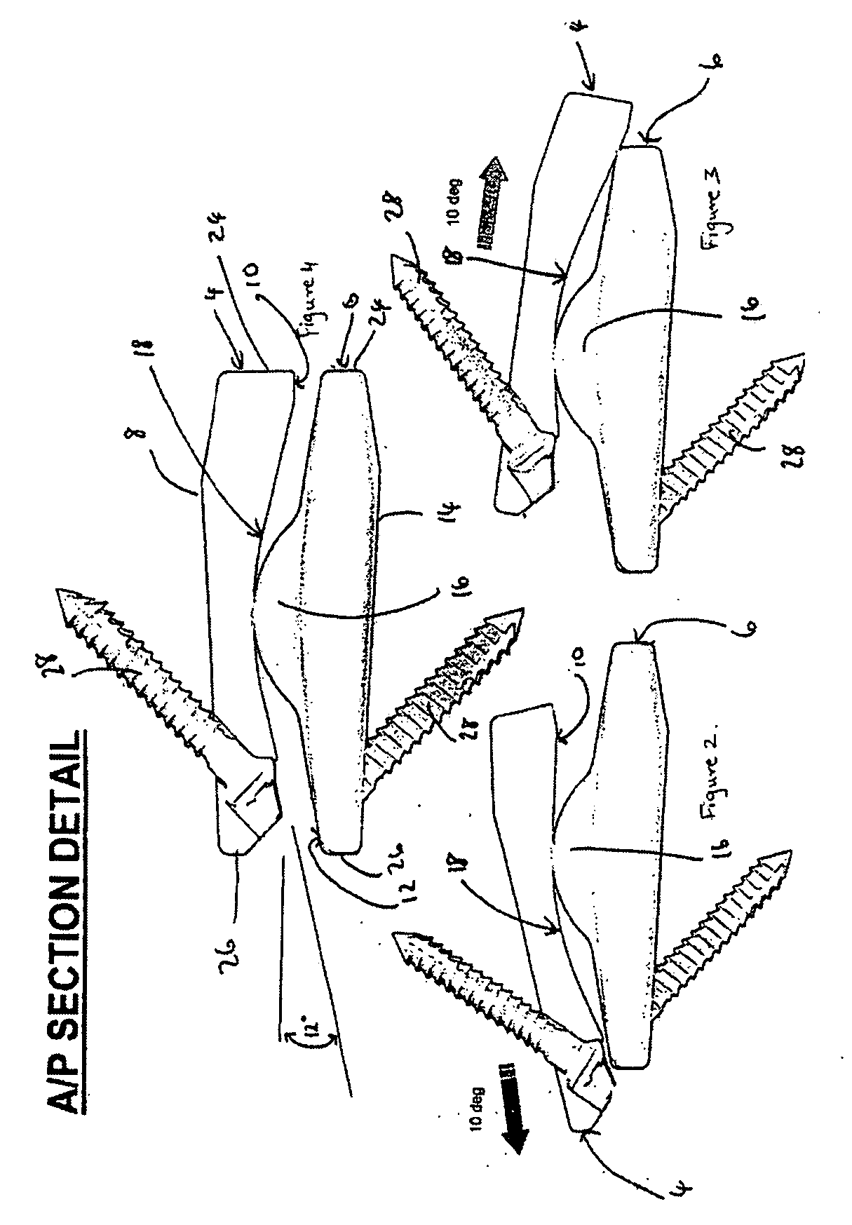
[0091] Referring firstly to FIGS. 1-30, there is illustrated a lumbar disc prosthesis 2 which can be inserted into a lumbar disc space via a posterior route as a replacement for a diseased and / or damaged lumbar disc.

[0092] The disc prosthesis 2 includes two pairs of disc members, each pair including an upper disc member 4, 4′ and a lower disc member 6, 6′.(Use of a reference numeral with ′ thereafter refers to a second or further feature equivalent to the feature indicated by the reference numeral alone. Thus, disc member 4 refers to the first prosthesis pair upper member and disc member 4′ refers to the second prosthesis pair upper member). The upper and lower disc members 4, 6; 4′, 6′ of each pair constitute a left and right disc prosthesis respectively. These disc members are shaped and dimensioned such that they can be inserted into a lumbar disc space either side of the dural sac whilst taking into account the posterior neural anatomy.

[0093] Each upper...


PUM

PropertyMeasurementUnit
Fractionaaaaaaaaaa
Angleaaaaaaaaaa
Radiusaaaaaaaaaa

Abstract

Lumbar disc and facet joint replacement prosthesis are provided. The lumbar disc prosthesis includes first member having a vertebral disc contact surface and a recessed portion on an opposing surface thereof and a second member having a vertebral disc contact surface and a protruding portion on an opposing surface thereof. The protruding portion of the second member engages the recessed portion of the first member in use. The first and second members are provided with at least a middle section and two end sections. The recessed and protruding portions are provided in the middle section of the respective members and each end section has a narrowing taper. The facet joint prosthesis includes a first member for attachment to a first posterior lumbar disc and a second member for attachment to a second posterior lumbar disc. At least a part of the first member is telescopically mounted in at least a part of the second member.

Description

REFERENCE TO PENDING APPLICATIONS [0001] This application claims priority to Great Britain Patent Application No. 0422963.9 filed Oct. 15, 2004. FIELD OF THE INVENTION [0002] This invention relates to devices and surgical methods for the treatment of various types of lumbar spine pathologies. It is specifically directed to the different types of degenerative pathologies in the lumbar spine. It deals with the development of an artificial facet joint, and an artificial lumbar disc replacement that is specifically designed to be inserted from a posterior approach to the spine. BACKGROUND OF THE INVENTION [0003] Back pain affects 40% of the population. Up to 20% of the population visit their family doctor requesting help with their back problem. Up to 30% of patients continue to complain of significant back pain at one year following the onset of their symptoms. [0004] Although the majority of patients have minor sprains or strains which are self limiting, a significant number of patien...

Claims


Application Information

Patent Timeline
IPC IPC(8): A61F2/44A61B17/70
CPCA61B17/7007A61F2310/00796A61B17/7025A61B17/7059A61B17/7064A61F2/30771A61F2/4405A61F2/4425A61F2/4611A61F2002/30112A61F2002/30156A61F2002/30286A61F2002/30331A61F2002/30367A61F2002/30369A61F2002/3037A61F2002/30372A61F2002/30373A61F2002/30507A61F2002/30578A61F2002/30601A61F2002/3065A61F2002/30654A61F2002/30828A61F2002/30841A61F2002/30884A61F2002/30934A61F2002/448A61F2002/449A61F2220/0025A61F2220/0033A61F2230/0004A61F2230/0023A61F2230/0063A61F2310/00017A61F2310/00023A61F2310/00179A61B17/7011
Inventor KRISHNA, MANOJFRIESEN, TAI
Owner DISC MOTION TECH
Why Eureka
Try Eureka