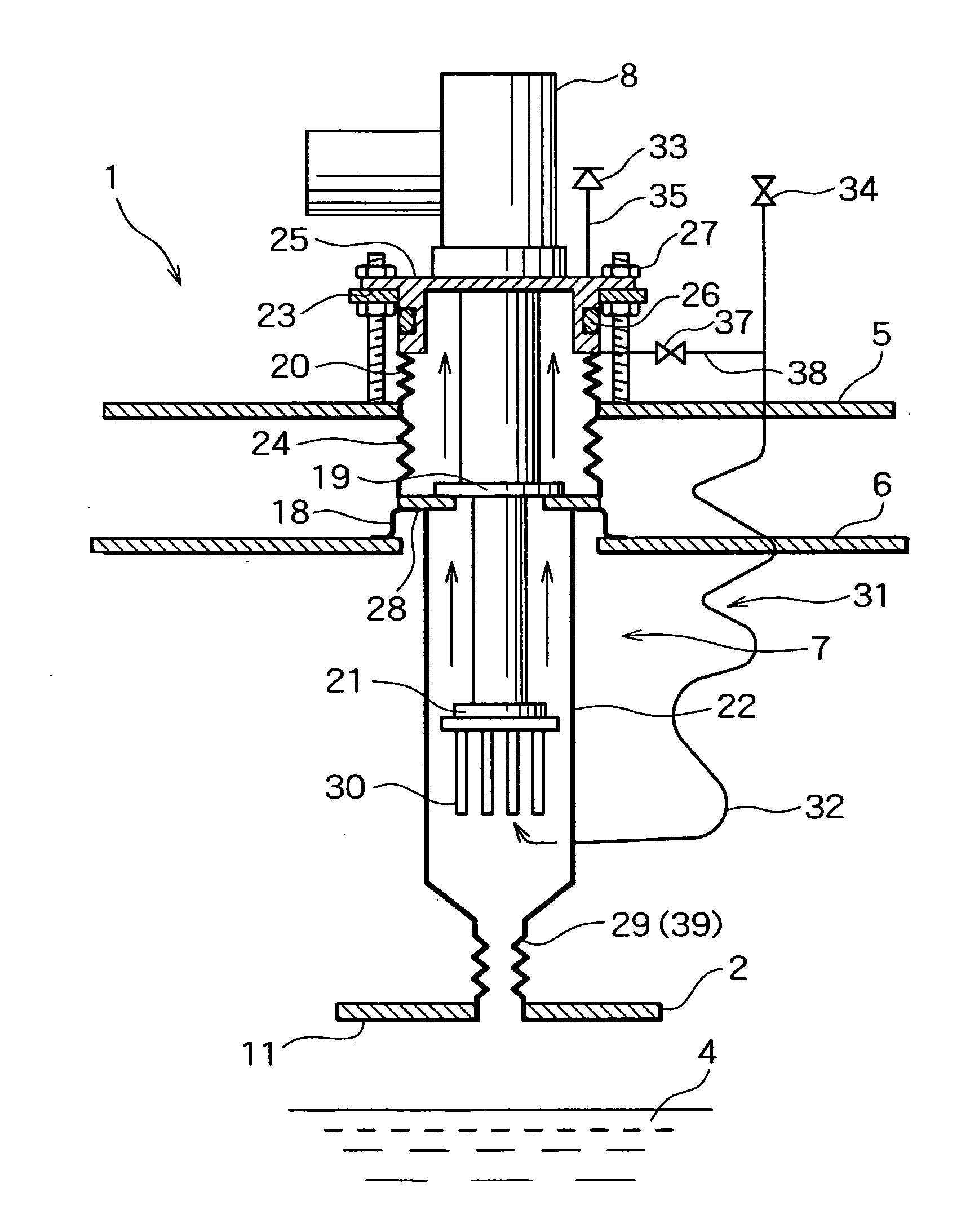
Cryogenic system
a cryogenic system and cryogenic technology, applied in the field of cryogenic systems, can solve problems such as polluting the refrigerator sleeve, and achieve the effect of preventing air from entering and ensuring replacemen
- Summary
- Abstract
- Description
- Claims
- Application Information
AI Technical Summary
Benefits of technology
Problems solved by technology
Method used
Image
Examples
first embodiment
[0051] the present invention will now be described with reference to drawings.
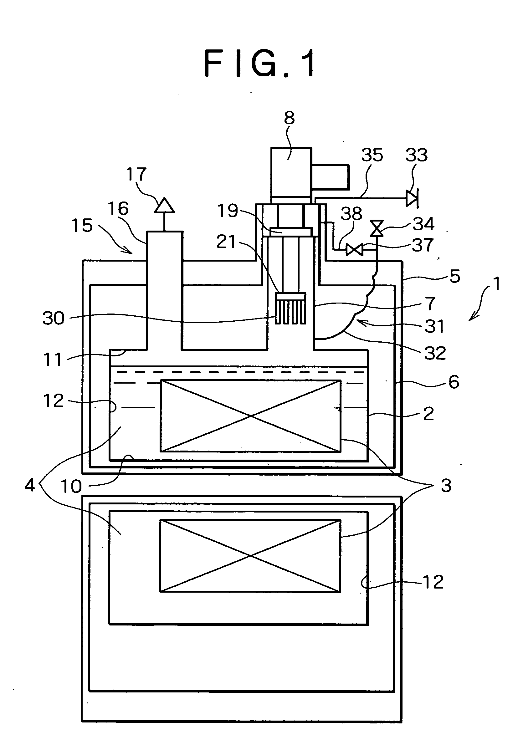
[0052]FIG. 1 is a schematic sectional view of MRI which is an example of a cryogenic system.
[0053] The cryogenic system 1 includes a containment vessel 2. The containment vessel 2 contains a superconducting magnet 3 that is a body to be cooled, the body being immersed in a liquid coolant 4 that is liquid helium. The containment vessel 2 is surrounded by a vacuum vessel 5 with a space present therebetween and the space is maintained under vacuum. A thermal shield 6 is placed in the space between the containment vessel 2 and the vacuum vessel 5 in such a manner that the thermal shield 6 surrounds the containment vessel 2.
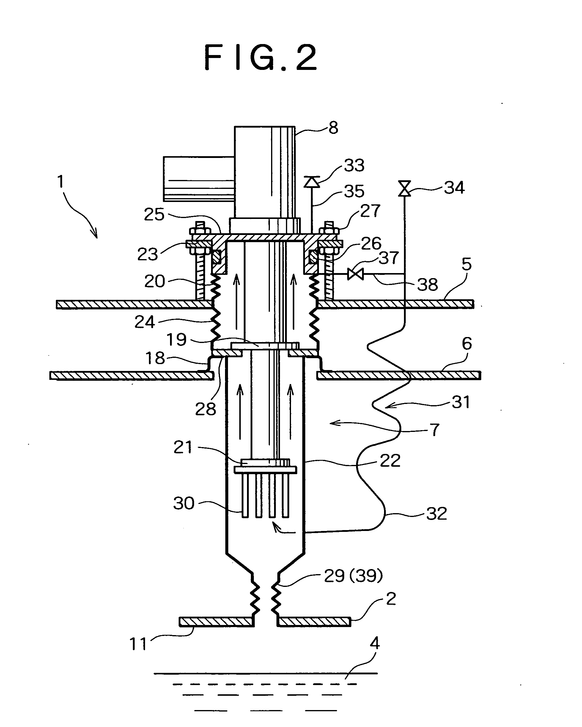
[0054] A tubular refrigerator sleeve 7 extends through the vacuum vessel 5 and the thermal shield 6. A base section of the refrigerator sleeve 7 is communicatively connected into the containment vessel 2 and an opening section of the refrigerator sleeve 7 is opening to the outside of the v...
second embodiment
[0095] A cryogenic system according to the present invention will now be described.
[0096] As shown in FIGS. 4 and 5, in the second embodiment, a gas-blocking means 39 is significantly different from that of the first embodiment; however, other components are substantially the same as those of the first embodiment.
[0097] That is, the gas-blocking means 39 includes a valve body 40 with which a base section of a refrigerator sleeve 7 can be blocked and which can be freely operated from outside.
[0098] That is, the valve body 40 is a copper disk which is provided in a connecting chamber 36 connected to a containment vessel 2 and which is placed below a connecting pipe 29. The valve body 40 includes a disk section 42, placed horizontally, for blocking an aperture section 41 placed between the connecting pipe 29 and the connecting chamber 36; a peripheral section 43 provided such that it perpendicularly extends downward from the edge of the disk section 42; and a flange section 44 extend...
third embodiment
[0105] A cryogenic system according to the present invention will now be described.
[0106] As shown in FIG. 6, in the third embodiment, a gas-blocking means 39 is significantly different from that of the second embodiment; however, other components are substantially the same as those of the second embodiment.
[0107] A valve body 40 does not have a disk shape but has a cone shape and an aperture section 41 has a funnel shape (such a shape as an ordinary funnel is upside down) such that a cone section 60 of the valve body 40 is fitted in the aperture section 41. The cone section 60 has a face in contact with the aperture section 41 and a plating layer 50, including two sub-layers, similar to that of the second embodiment is formed on this face.
[0108] Since the valve body 40 has such a cone shape as described above, the valve body 40 has a large area in contact with the aperture section 41; hence, the aperture section 41 can be securely sealed with the valve body 40.
PUM
| Property | Measurement | Unit |
|---|---|---|
| cryogenic temperature | aaaaa | aaaaa |
| temperature | aaaaa | aaaaa |
| temperature | aaaaa | aaaaa |
Abstract
Description
Claims
Application Information
 - R&D
- Intellectual Property
- Life Sciences
- Materials
- Tech Scout
- Unparalleled Data Quality
- Higher Quality Content
- 60% Fewer Hallucinations
Browse by: Latest US Patents, China's latest patents, Technical Efficacy Thesaurus, Application Domain, Technology Topic, Popular Technical Reports.
© 2025 PatSnap. All rights reserved.Legal|Privacy policy|Modern Slavery Act Transparency Statement|Sitemap|About US| Contact US: help@patsnap.com


