Precision pyrotechnic display system and method having increased safety and timing accuracy

a pyrotechnic display and timing accuracy technology, applied in the direction of launching weapons, ammunition fuzes, electric fuzes, etc., can solve the problems of time delay, preventing the industry from achieving the timing accuracy and repeatability necessary for precisely choreographed pyrotechnic displays, and difficulty in controlling the delay time of a black powder fuse to better than +/ 1%, so as to increase the safety of the pyrotechnic display and reduce the potential of mis

Inactive Publication Date: 2006-04-27
BOSSARTE GEORGE +1
View PDF54 Cites 24 Cited by
  • Summary
  • Abstract
  • Description
  • Claims
  • Application Information

AI Technical Summary

Benefits of technology

[0014] In a broad sense, the present invention describes a method and system for controlling the launch and burst of pyrotechnic projectiles in a pyrotechnic display. More particularly, the present invention describes a method and system for increasing the safety and improving the accuracy of ignition timing for pyrotechnic displays.
[0016] A further object of the present invention is to provide the capability to use standard pyrotechnic projectiles with black powder fuses for some, but not all, of the pyrotechnic display. Thus pyrotechnic operators can mix pyrotechnic shells utilizing the present invention with more conventional pyrotechnic shells in order to achieve the most cost-effective pyrotechnic display possible.
[0017] A further object of the present invention is to increase the safety of the pyrotechnic display for both the pyrotechnic operator and the viewing audience. A further object of the present invention is to reduce the potential of misfires and crossfires (i.e., the ignition of a projectile by the ignition products of nearby shells) by eliminating the traditional black powder fuse. A further object of the present invention is to reduce the potential of hangfires (i.e., shells that explode after returning to the ground).
[0018] A further object of the present invention is to provide the capability of reporting to the pyrotechnic operator the existence of faults within the system and to indicate which shells will not have their lift charge ignited because of the presence of these faults.
[0019] A further object of the present invention is to provide the capability to use multiple shells on the same ignition output and to provide the capability of reporting to the pyrotechnic operator the existence of faults in any of the individual shells.
[0020] While the present invention is presently intended primarily for use in improved pyrotechnic displays, the invention's advantages of increased safety and timing accuracy may be applied to other fields as well, such as construction and explosive demolition.

Problems solved by technology

The ignition of the lift charge also ignites a second black powder fuse, which provides a time delay to allow the projectile to reach a desired height above the ground.
Although black powder-based ignition systems are relatively easy to use, the fundamental limitations of the black powder fuse prevent the industry from achieving the timing accuracy and repeatability necessary for precisely choreographed pyrotechnic displays.
Controlling the delay time for a black powder fuse to better than + / − 1% is extremely difficult; and even if this accuracy could be reliably achieved, it would still contribute to a total variability of 100 milliseconds for a 5-second fuse.
Achieving such accuracy is impossible with black powder fuses.
In addition, the inherent limitations of the black powder fuse also provide a source of potential failures that present real risk to both the display operators and the proximate audience.
However, the use of a black powder fuse for the lift charge necessitates the exposure of the black powder to the external environment of the shell.
Consequently the shell becomes much more sensitive to false ignition by burning materials from nearby pyrotechnic shells, resulting in unintentional “crossfire”.
If the lift charge of a shell is ignited but the time delay fuse to the break charge burns too slowly, a “hangfire” occurs, in which the shell explodes as it returns to the ground, often near the display operator or in the audience.
Even more dangerous, if a hangfire explodes after the shell hits the ground, both the explosion and the falling shell itself present significant risks to the operator and audience.
If a fuse fails to ignite the lift charge, but the fuse continues to burn and ignites the break charge while the shell is still on the ground, a “mortar burst” can occur, and the ignition products of the break can potentially ignite the break charges of all the adjacent shells of the display.
A break charge being ignited on the ground can result in serious injury to the operating personnel as well as the destruction of the entire display.
Such use of the e-match reduces the likelihood of crossfires, but does nothing to improve the timing of the break since a black powder delay fuse would still be required to ignite the break charge.
On the other hand, U.S. Pat. No. 5,627,338 by Poor et al., U.S. Pat. No. 5,623,117 by Lewis, U.S. Pat. No. 5,499,579 by Lewis, U.S. Pat. No. 5,335,598 by Lewis et al., U.S. Pat. No. 4,363,272 by Simmons, U.S. Pat. No. 4,239,005 by Simmons, and U.S. Pat. No. 4,068,592 by Beuchat describe methods to delay the firing action of an e-match based on electrical or pyrotechnic delays, but none of these methods are suitable to achieving the high accuracy required for choreographed displays.
A method of using an e-match is described by Poor et al. in U.S. Pat. No. 5,627,338, but even this technique is limited to about 25 milliseconds variability, which is still a factor of 25 worse than the desired 1 millisecond variability previously discussed.
A number of problems or faults can occur during the setup of a choreographed pyrotechnic display.
The pyrotechnic operator cannot easily detect many of these problems.
If e-matches are used to replace the black powder fuses, new problems unique to e-matches are possible.
For example, if e-matches are used to ignite the black powder lift charges, the electrical connections to the e-matches may be faulty.
If multiple e-matches are wired in parallel to a single electrical ignition source, the possibility exists that some e-matches will not be connected properly.
On the other hand, if multiple e-matches are wired in series, the possibility exists that the electrical ignition source will be insufficient to ignite all of the e-matches.
If e-matches are used to ignite both the lift and break charges, additional problems may develop.
For example, either or both of the e-matches may have broken wires.
Furthermore, since an energy source is required to fire both e-matches (and the source for the break match must travel with the projectile), the possibility exists that either energy source may be insufficient to ignite its corresponding e-match.
If, for example, the lift energy source is sufficient to ignite the lift charge, but the break energy source is not sufficient to ignite the break charge, a dangerous hangfire can result, with significant risk to the pyrotechnic operator and the audience.

Method used


Image

  • Precision pyrotechnic display system and method having increased safety and timing accuracy
  • Precision pyrotechnic display system and method having increased safety and timing accuracy
  • Precision pyrotechnic display system and method having increased safety and timing accuracy

Examples


Embodiment Construction

[0029] The present invention involves a system and method for controlling the launch and burst of pyrotechnic projectiles in a pyrotechnic, or “fireworks,” display.

Pyrotechnic Projectile

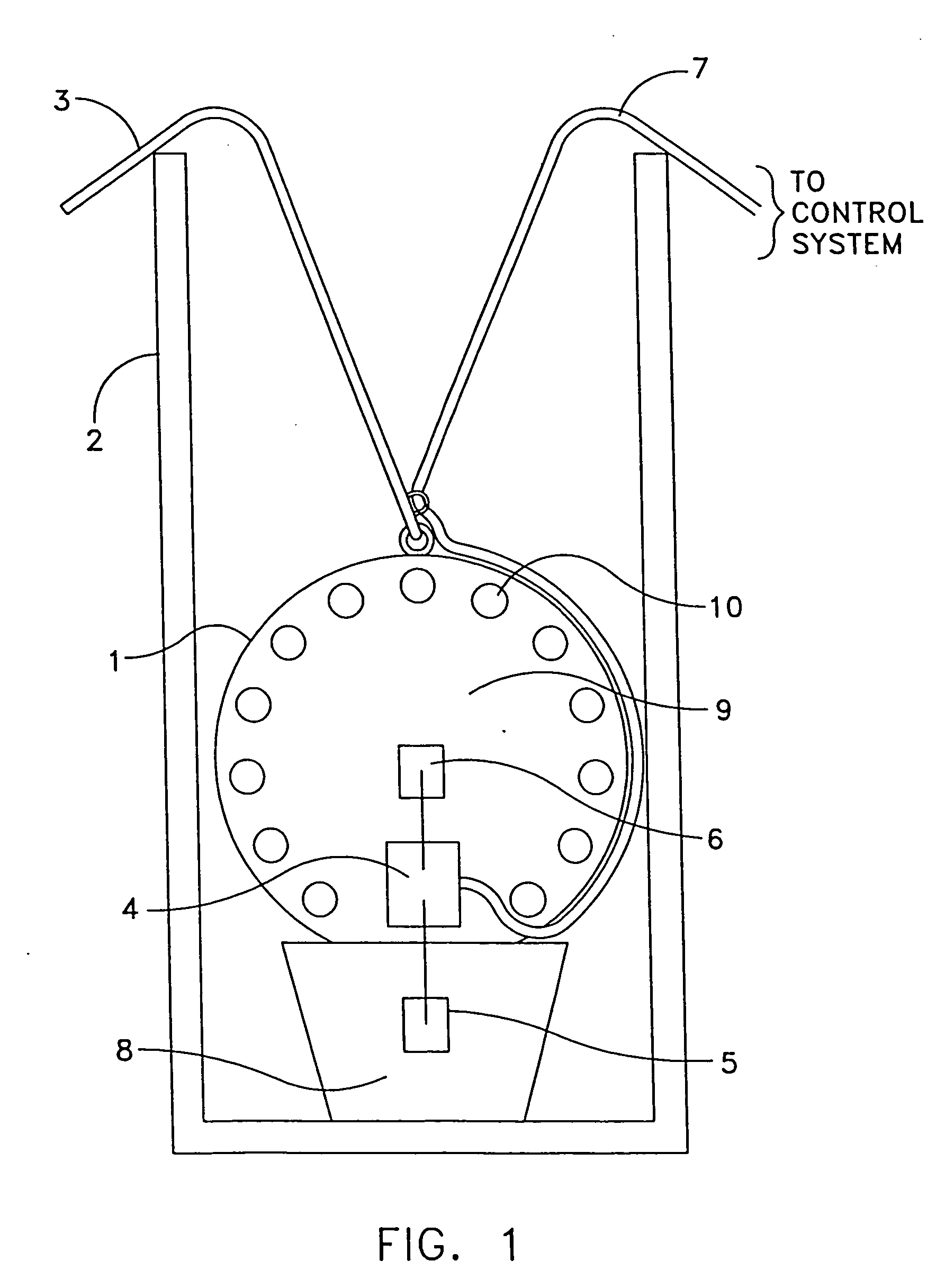
[0030]FIG. 1 shows a typical pyrotechnic projectile 1 placed in mortar 2. Projectile 1 utilizes load cord 3 to allow the pyrotechnic operator to easily place the projectile into mortar 2. Embedded inside projectile 1 is ignitor 4 which is connected to the lift electric match (e-match) 5 and to the break e-match 6. Wires 7 connect ignitor 4 to the pyrotechnic control system. Lift e-match 5 is embedded in lift charge 8, which is typically made of black powder. Lift charge 8, when ignited, provides the force to propel projectile 1 high into the air. Break e-match 6 is embedded in break charge 9, which is also typically made of black powder. Break charge 9, when ignited by break e-match 6, causes projectile 1 to burst and provide the visual or auditory effect desired. Projectile 1 may contain additiona...


PUM


Abstract

A system and method are disclosed for controlling the launch and burst of pyrotechnic projectiles in a pyrotechnic, or “fireworks”, display.

Description

REFERENCE TO PENDING PRIOR PATENT APPLICATIONS [0001] This patent application: [0002] (1) is a continuation-in-part of pending prior U.S. patent application Ser. No. 10 / 958,721, filed Oct. 5, 2004 by George Bossarte et al. for PRECISION PYROTECHNIC DISPLAY SYSTEM AND METHOD HAVING INCREASED SAFETY AND TIMING ACCURACY (Attorney's Docket No. MAG-4 DIV CON), which is in turn a continuation of prior U.S. patent application Ser. No. 10 / 313,879, filed Dec. 6, 2002 by George Bossarte et al. for PRECISION PYROTECHNIC DISPLAY SYSTEM AND METHOD HAVING INCREASED SAFETY AND TIMING ACCURACY (Attorney's Docket No. MAG-4 DIV), which is in turn a divisional of prior U.S. patent application Ser. No. 09 / 281,203, filed Mar. 30, 1999 by George Bossarte et al. for PRECISION PYROTECHNIC DISPLAY SYSTEM AND METHOD HAVING INCREASED SAFETY AND TIMING ACCURACY (Attorney's Docket No. MAG-4), which in turn claims the benefit of (i) U.S. Provisional Patent Application Ser. No. 60 / 079,853, filed Mar. 30, 1998 by ...

Claims


Application Information

Patent Timeline
Patent Type & Authority Applications(United States)
IPC IPC(8): F42D1/055
CPCF41A19/58F41A19/65F41A19/68F41F1/06F42B4/00F42B4/02F42B30/10F42C11/00F42C11/008F42C15/42F42D1/05F42D1/055F42B4/24F42C19/0815
Inventor BOSSARTE, GEORGEMCKINLEY, PAUL R.
Owner BOSSARTE GEORGE
Why Eureka
Try Eureka