

Solar concentrator
- Summary
- Abstract
- Description
- Claims
- Application Information
AI Technical Summary
Benefits of technology
Problems solved by technology
Method used
Image

Examples
Embodiment Construction
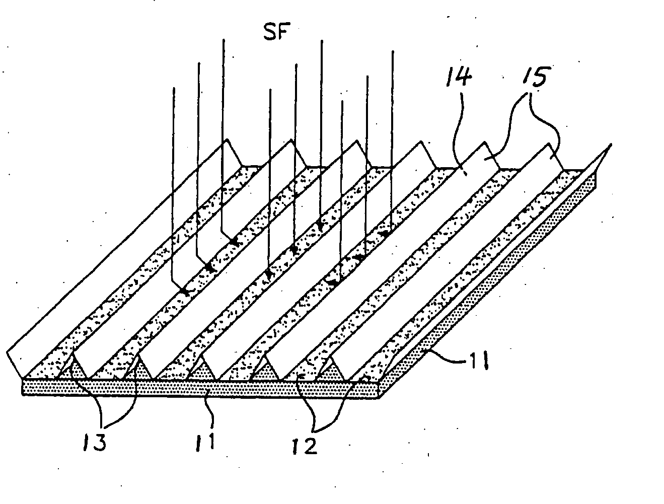
[0028] Referring to FIG. 1, there is illustrated a solar concentrator following the present invention. Rows of saw tooth reflectors 13 and solar cells 12 are alternatively presented. They are mounted on the solar panel structure 11, such as a honeycomb panel structure by adapted fasteners. This structure is usually made of an aluminum honeycomb with CFRP (Carbon Fiber Reinforced Polymer) face sheets on both sides. The solar radiation is incident on the panel structure 11. It will reach the solar cells 12 either directly or after reflection on the reflective coating of the reflectors 13. In one preferred embodiment, the row widths are similar for the solar cells 12 and the reflectors 13, depending on the geometric concentration factor. For example, the widths are identical when the geometric concentration factor is 2:1. The reflector inclination angle depending on the geometric concentration factor is about 60 degrees and it is exactly 60 degrees when the geometric concentration fact...
PUM
 Abstract
Description
Claims
Application Information