Electric drive system for vehicle, electric control system for vehicle, electric drive method for vehicle

a technology of electric control system and electric drive method, which is applied in the direction of electric propulsion mounting, battery/cell propulsion, transportation and packaging, etc., to achieve the effect of improving driving efficiency

Inactive Publication Date: 2006-04-27
HITACHI LTD +1
View PDF11 Cites 42 Cited by
  • Summary
  • Abstract
  • Description
  • Claims
  • Application Information

AI Technical Summary

Benefits of technology

[0008] According to the present invention, since the energy generated during a retardation is converted to thermal energy which is discharged to the air by cooling, the present invention is effective particularly when the retardation is continuously applied, and can improve the driving efficiency.

Problems solved by technology

However, the prior art described above publication difficulties in absorbing energy generated during a retardation of the vehicle as the energy generated during the retardation becomes larger when the vehicle continuously runs down a long downhill.

Method used


Image

  • Electric drive system for vehicle, electric control system for vehicle, electric drive method for vehicle
  • Electric drive system for vehicle, electric control system for vehicle, electric drive method for vehicle
  • Electric drive system for vehicle, electric control system for vehicle, electric drive method for vehicle

Examples


Embodiment Construction

[0018] In the following, several embodiments of the present invention will be described with reference to the accompanying drawings.

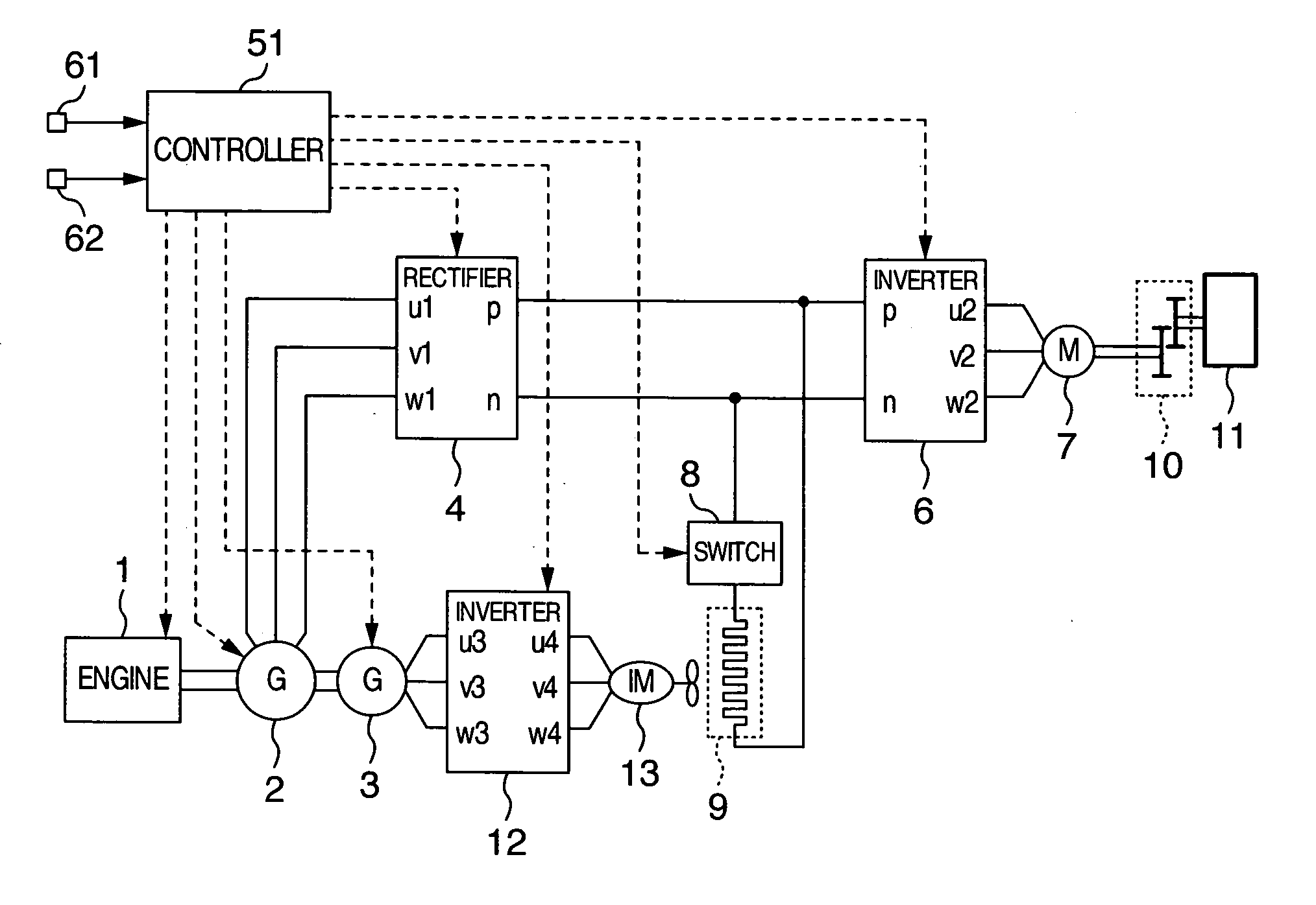
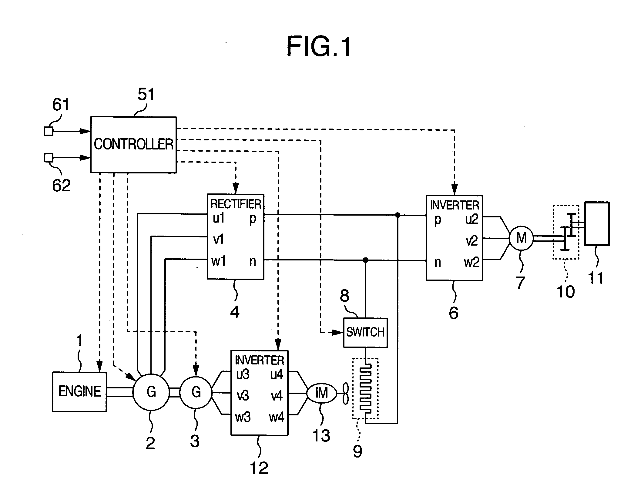
[0019] Describing in brief the configuration of an electric drive system for a vehicle according to a first embodiment, the electric drive system comprises a blower for cooling down a retard resistor in this embodiment. The blower is driven by an associated inverter which is powered by an auxiliary alternator coaxial with a main alternator. Also, the auxiliary alternator is controlled to generate a constant output voltage irrespective of the engine rotation speed, so that the retard resistor can be cooled down under an optimal cooling condition, irrespective of the engine rotation speed and conditions under which the main alternator generates the electric power.

[0020] Describing specifically with reference to FIG. 1, the main alternator 2 and auxiliary alternator 3 are driven by the engine 1. The output of the main alternator 2 is converted to a direc...


PUM


Abstract

In an electric drive system for a vehicle, an alternator is driven by an engine to generate electric power which is used to drive a motor to generate a driving force. During a retardation of the vehicle, the motor is operated as an alternator to convert kinetic energy to electric energy which is used to retard the vehicle. A retard resistor is provided for absorbing electric energy generated during the retardation state. The retard resistor is cooled down by an AC blower.

Description

BACKGROUND OF THE INVENTION [0001] The present invention relates to an electric drive system for a vehicle, an electric control system for a vehicle, and an electric drive method for a vehicle. [0002] For electrically driving a vehicle, an engine is used to generate power with which an alternator is driven to generate electric power which is used to drive a motor for moving the vehicle. Specifically, the alternator is driven by the engine to generate electric power which is then converted to a direct current (DC) by a rectifier, and the DC power is supplied to an inverter. Further, the DC input is converted to an alternate current (AC) output by the inverter, an AC motor is driven with the AC output to rotate wheels through gears, thus driving a vehicle to move. [0003] For retarding a vehicle, the AC motor is operated as an alternator, while the inverter is operated as a converter to convert AC power to DC power. Such a technique is described, for example, in JP-A-2000-224709. SUMMA...

Claims


Application Information

Patent Timeline
Patent Type & Authority Applications(United States)
IPC IPC(8): B60K1/00B60L1/00B60L50/14B60L7/06
CPCB60L7/22B60L11/123B60L2210/20Y10S903/947Y02T10/7077Y02T10/725Y02T10/6217B60L50/61Y02T10/62Y02T10/72Y02T10/70Y02T10/7072
Inventor SHIMADA, KEIZOKIYOFUJI, YASUHIROSUGAWARA, NAOSHIIMAIE, KAZUHIROOKU, SHINTAROUYAGYU, TAKASHI
Owner HITACHI LTD
Why Eureka
Try Eureka