Deposited semiconductor structure to minimize N-type dopant diffusion and method of making

a semiconductor structure and n-type technology, applied in semiconductor devices, diodes, electrical devices, etc., can solve problems such as adversely affecting device behavior

Active Publication Date: 2006-04-27
SANDISK TECH LLC
View PDF8 Cites 206 Cited by
  • Summary
  • Abstract
  • Description
  • Claims
  • Application Information

AI Technical Summary

Benefits of technology

[0006] A first aspect of the invention provides for a semiconductor device comprising a layerstack, the layerstack comprising: a first layer of deposited heavily n-doped semiconductor material above a substrate, the first layer at least about 50 angstroms thick; a second layer of semiconductor material which is not heavily n-doped, wherein the semiconductor material of the second layer is a silicon-germanium alloy that is at least 10 at % germanium, the second layer at least about 100 angstroms thick, wherein the second layer is above and in contact with the first layer; and a third layer of deposited semiconductor material which is not heavily n-doped above and in contact with the second layer, wherein the semiconductor material of the third layer is silicon or a silicon-germanium alloy that is less than 10 at % germanium, wherein the first, second, and third layers reside in a semiconductor device.
[0007] Another aspect of the invention provides for a nonvolatile memory cell formed above a substrate, the memory cell comprising: a portion of a bottom conductor above the substrate; a portion of a top conductor above the bottom conductor; and a diode vertically disposed between the bottom conductor and the top conductor, the diode comprising: i) a first deposited layer of heavily n-doped semiconductor material; ii) a second deposited layer of semiconductor material which is not heavily n-doped wherein the semiconductor material of the second layer is a silicon-germanium alloy that is at least 10 at % germanium, the second layer disposed above and in contact with the first layer; and iii) a third deposited layer of semiconductor material which is not heavily n-doped, wherein the semiconductor material of the third layer is silicon or a silicon-germanium alloy that is less than 10 at % germanium, wherein the third layer is above and in contact with the second layer.
[0

Problems solved by technology

This unwanted n-type dopant may

Method used


Image

  • Deposited semiconductor structure to minimize N-type dopant diffusion and method of making
  • Deposited semiconductor structure to minimize N-type dopant diffusion and method of making
  • Deposited semiconductor structure to minimize N-type dopant diffusion and method of making

Examples


example

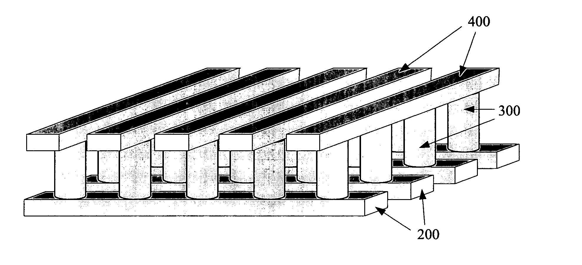
[0039] Fabrication of a single memory level will be described in detail. Additional memory levels can be stacked, each monolithically formed above the one below it.

[0040] Turning to FIG. 7a, formation of the memory begins with a substrate 100. This substrate 100 can be any semiconducting substrate as known in the art, such as monocrystalline silicon, IV-IV compounds like silicon-germanium or silicon-germanium-carbon, III-V compounds, II-VII compounds, epitaxial layers over such substrates, or any other semiconducting material. The substrate may include integrated circuits fabricated therein.

[0041] An insulating layer 102 is formed over substrate 100. The insulating layer 102 can be silicon oxide, silicon nitride, high-dielectric film, Si—C—O—H film, or any other suitable insulating material.

[0042] The first conductors 200 are formed over the substrate and insulator. An adhesion layer 104 may be included between the insulating layer 102 and the conducting layer 106 to help the con...


PUM


Abstract

In deposited silicon, n-type dopants such as phosphorus and arsenic tend to seek the surface of the silicon, rising as the layer is deposited. When a second undoped or p-doped silicon layer is deposited on n-doped silicon with no n-type dopant provided, a first thickness of this second silicon layer nonetheless tends to include unwanted n-type dopant which has diffused up from lower levels. This surface-seeking behavior diminishes when germanium is alloyed with the silicon. In some devices, it may not be advantageous for the second layer to have significant germanium content. In the present invention, a first heavily n-doped semiconductor layer (preferably at least 10 at % germanium) is deposited, followed by a silicon-germanium capping layer with little or no n-type dopant, followed by a layer with little or no n-type dopant and less than 10 at % germanium. The germanium in the first layer and the capping layer minimizes diffusion of n-type dopant into the germanium-poor layer above.

Description

RELATED APPLICATION [0001] This application is a continuation-in-part of Herner et al., U.S. application Ser. No. 10 / 954,577, “Junction Diode Comprising Varying Semiconductor Compositions,” filed Sep. 29, 2004, hereinafter the '577 application and hereby incorporated by reference in its entirety.BACKGROUND OF THE INVENTION [0002] The invention relates to a deposited vertical semiconductor layerstack that serves to minimize surfactant behavior of n-type dopants, and the methods of making the layerstack. [0003] During deposition of silicon, n-type dopants such as phosphorus and arsenic tend to seek the surface, rising through a silicon layer as it is deposited. If it is desired to deposit a layer having little or no n-dopant (an undoped or p-doped layer, for example) immediately above a heavily doped n-type layer, this tendency of n-type dopant atoms to diffuse toward the surface introduces unwanted dopant into the undoped or p-doped layer. This unwanted n-type dopant may adversely af...

Claims


Application Information

Patent Timeline
IPC IPC(8): H01L31/117H01L29/00
CPCH01L27/1021H01L29/161H01L29/165H01L45/08H01L27/2463H01L45/1233H01L45/145H01L45/146H01L27/2409H01L45/04H10B63/20H10B63/80H10N70/20H10N70/883H10N70/8833H10N70/826H10N70/24
Inventor HERNER, S. BRAD
Owner SANDISK TECH LLC
Why Eureka
Try Eureka