System for airflow management in electronic enclosures

a technology of airflow management and electronic enclosure, which is applied in the direction of electrical apparatus casings/cabinets/drawers, lighting and heating apparatus, instruments, etc., can solve the problems of difficulty in cooling these cards and cec boards, ics generate significant amounts of heat, etc., to facilitate installation and removal of daughters, facilitate front-to-back airflow, and facilitate front-to-back airflow

Active Publication Date: 2006-04-27
IBM CORP
View PDF11 Cites 45 Cited by
  • Summary
  • Abstract
  • Description
  • Claims
  • Application Information

AI Technical Summary

Benefits of technology

[0014] In addition, the disclosed embodiments relate to central electronics complex including an enclosure and a backplane assembly vertically disposed within the enclosure and having at least one backplane connector. At least one daughter card includes a daughter card connector configured to be removably connectable to the backplane connector. The daughter card is oriented substantially perpendicular to the backplane assembly so that cooling air flows substantially parallel to the daughter card. At least one guide rail extends from the backplane assembly for operable communication with the enclosure. The guide rail facilitates installation and removal of the daughter card. Components disposed on the daughter card are oriented to facilitate front-to-back airflow, wherein inlet cooling air impinges on the backplane assembly and splits into at least two flow portions flowing in different directions along a surface defining the backplane assembly.
[0015] The disclosed embodiment

Problems solved by technology

Problems have arisen, for example, with the advent of employing daughter cards such as the large massive Processor-Memory cards.
However, inherent in such an architecture are difficulties in cooling these cards and CEC board.
As is well known, ICs generate significant amounts of heat during the course of their normal operation.
Air cooling multiple high powered MCMs in series along the midplane is ineffective due to air temperature rise and serial airflow impedances.
Since high-end server performance often requires placing numerous high powered logic modules in close proximity to a common vertical midplane, prior art central electronic complexes (CECs) have been unable to be air cooled in such an arrangement due to an

Method used


Image

  • System for airflow management in electronic enclosures
  • System for airflow management in electronic enclosures
  • System for airflow management in electronic enclosures

Examples


Embodiment Construction

[0033] The invention will now be described in more detail by way of example with reference to the embodiments shown in the accompanying figures. It should be kept in mind that the following described embodiments are only presented by way of example and should not be construed as limiting the inventive concept to any particular physical configuration.

[0034] Further, if used and unless otherwise stated, the terms “upper”, “lower”, “front”, “back”, “over”, “under”, and similar such terms are not to be construed as limiting the invention to a particular orientation. Instead, these terms are used only on a relative basis. For the purposes of the present disclosure, the terms printed circuit board (PCB) and printed wire board (PWB) are equivalent terms.

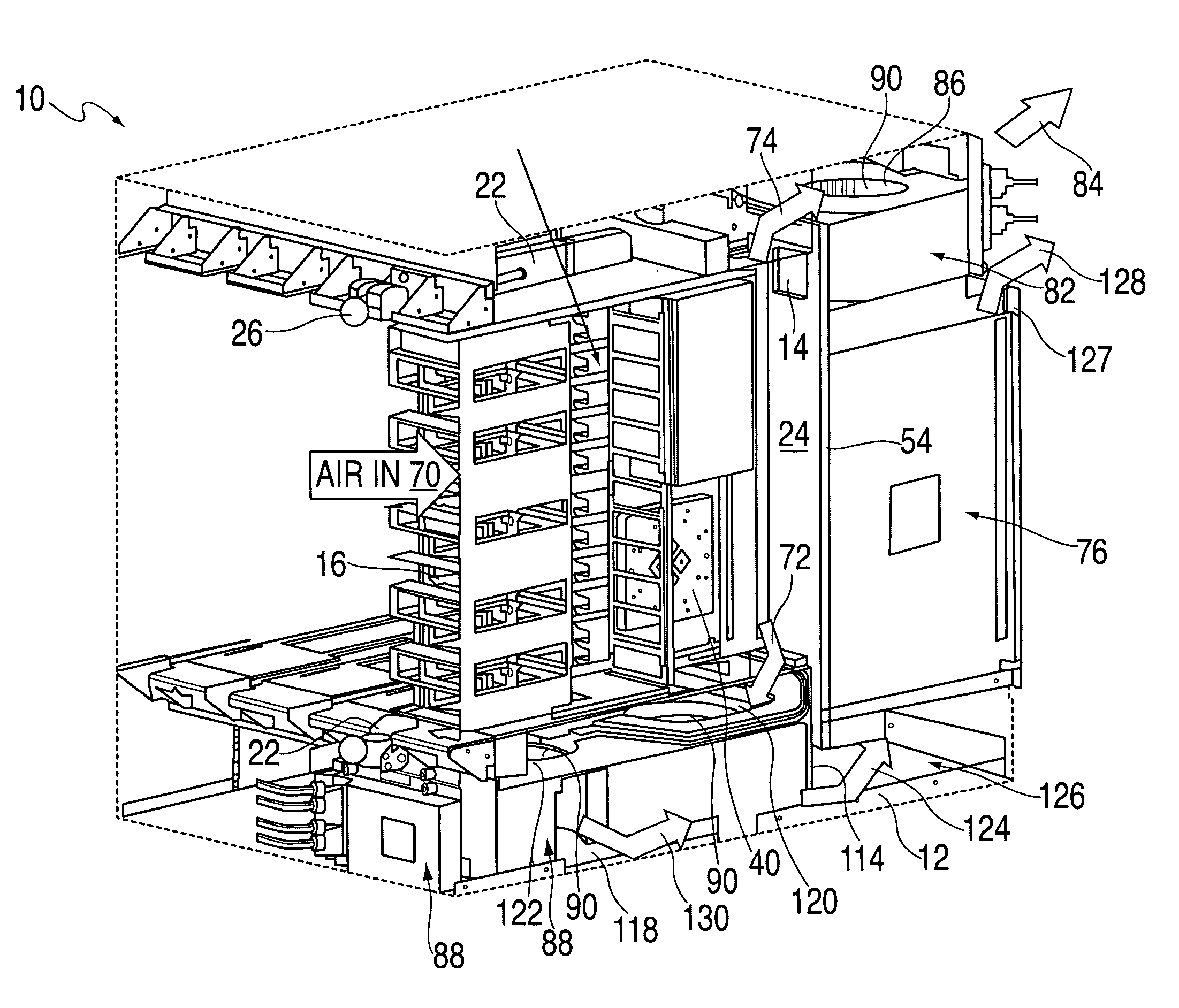
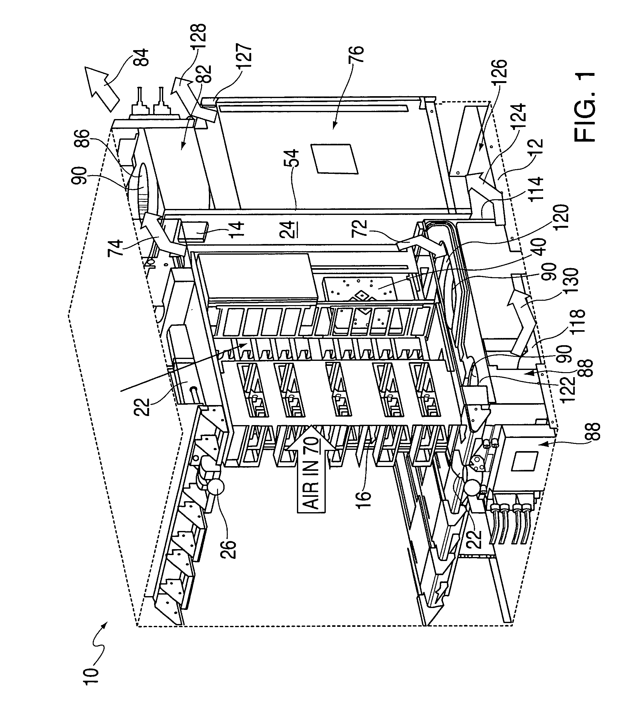
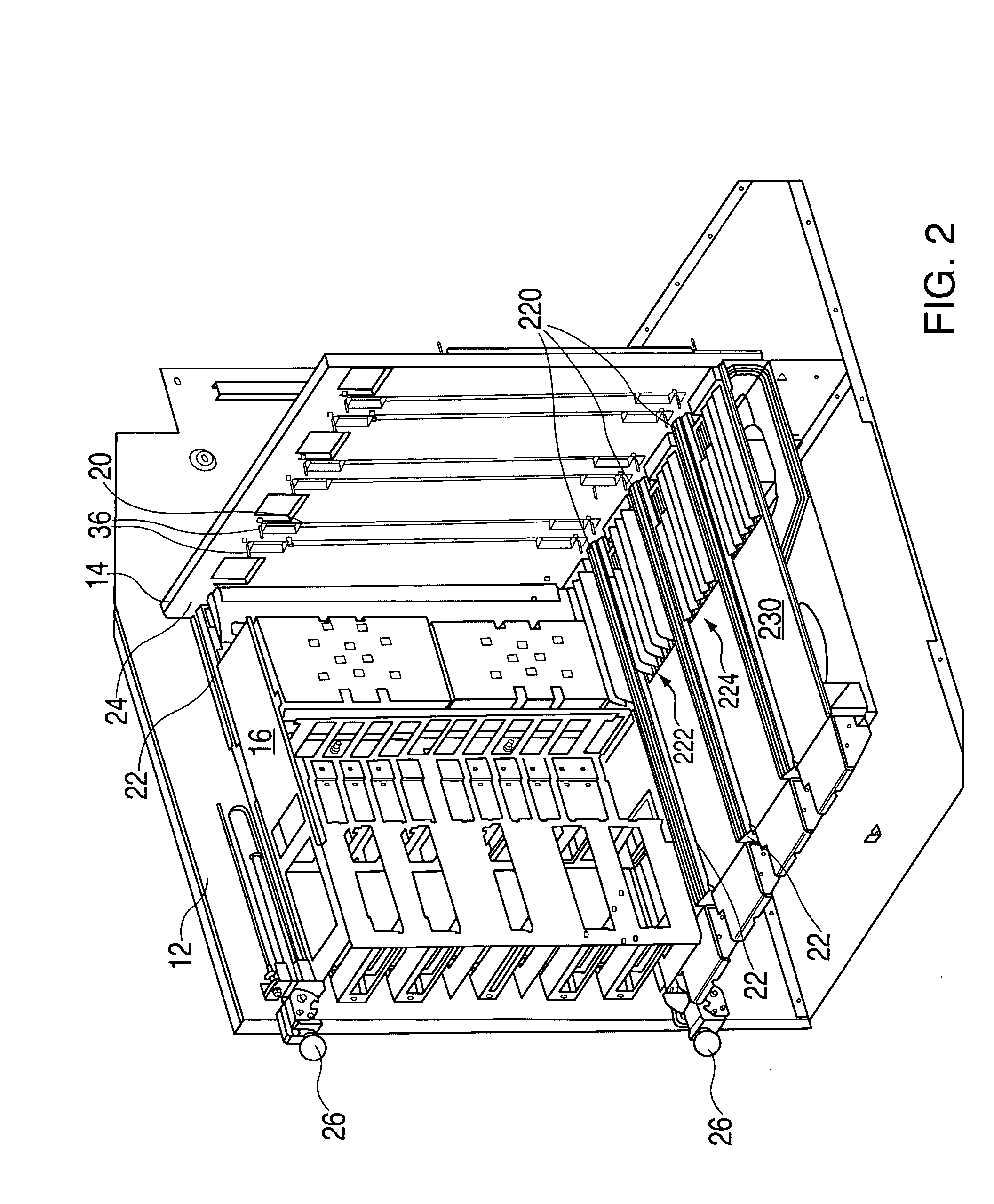
[0035]FIGS. 1 and 2 illustrate an exemplary embodiment of the invention, which includes a so-called central electronics complex 10 (CEC) of a computer system. The CEC 10 is comprised of an enclosure (such as a cage 12), a backplane or mid...


PUM


Abstract

A system for airflow management in an electronic enclosure includes a backplane assembly having at least one backplane connector, at least one daughter card, and components disposed on the daughter card oriented to facilitate front-to-back airflow, wherein inlet cooling air impinges on the backplane assembly and splits into at least two flow portions flowing in different directions along a surface defining the backplane assembly

Description

BACKGROUND OF THE INVENTION [0001] Computers are customarily provided with computer cage structures, which may comprise a sheet metal framework and which may contain a backplane. A backplane is a circuit board (e.g., mother card) or framework that supports other circuit boards, devices, and the interconnections among devices, and provides power and data signals to supported devices. The mother card may be the main circuit card in the computer, which may interconnect additional logical cards and assemblies. The computer cage structure is adapted to receive and removably support at least one and preferably a plurality of options or daughter cards (blades or nodes) which when operatively installed in their associated cage structure, upgrade the operating capabilities of the computer. For example, it is known to place an assembly, including a backplane and various circuit boards, such as a processor card, an input-output card and a so-called memory riser card, within an open cage. This ...

Claims


Application Information

Patent Timeline
IPC IPC(8): H05K1/00
CPCG06F1/183G06F1/20H05K7/20563
Inventor BECKER, WIREN D.CORRADO, JOSEPH P.CRUZ, ETHAN E.FISHER, MICHAEL J.GOTH, GARY F.
Owner IBM CORP
Why Eureka
Try Eureka