Embedded imaging and control system

a control system and imaging technology, applied in the field of imaging systems, can solve the problems of large system size, high cost of all these systems, and inability to use in embedded applications, and achieve the effect of convenient fi

Active Publication Date: 2006-04-27
PARATA SYST
View PDF100 Cites 74 Cited by
  • Summary
  • Abstract
  • Description
  • Claims
  • Application Information

AI Technical Summary

Benefits of technology

[0015] The vision system according to the present disclosure is a stand alone miniature imaging system that could capture undistorted, high resolution, stop-action images of objects moving at automation speeds, process the images in real time, and then perform real-time I / O based control that is a function of the image processing results. The system also has a miniature form factor so that it could be embedded inside a product. Ideally, the device would fit easily in the palm of a person's hand. The imaging system would have a flexible I / O system so that a variety of different applications could be met by changing only the programming and the external hardware connected to the device in which the imaging system is embedded. The device may be built at a cost of several hundred dollars or less in retail quantities.

Problems solved by technology

However, the vision-based inspection requirements of a pharmaceutical production facility are significantly different from those of a retail pill counting and dispensing machine that would be used in a central fill facility, mail order pharmacy, hospital or other health care related institution.
As a result, the vision mechanism used in a pharmaceutical production facility is not an embedded piece of equipment.
Although vision-based inspection mechanisms do exist for use in automation applications, all of these systems cost on average $4,000.
These systems are much too large to be used in an embedded application.
In fact, these mechanisms are larger than most of the pill counting and inspection products.
However, these systems are unsuitable for many embedded applications because external hardware is required to evaluate the processed image and / or initiate I / O control of external devices based on the results of the evaluation.
This type of vision mechanism usually uses large adjustable stock lenses and is encased in a metal box which makes the unit physically too large for embedded applications.
Although this image processor output may be used to perform rudimentary control, the device does not contain a controller and there are no resident controller algorithms.
These devices are typically too large for embedded use and they do not have an I / O controller or controller programming capability, only several bits of image pass / fail results, which may or may not be usable for process control.
Although the image processor in such devices uses variables, which a user may set, the image processing is hardware coded and cannot be altered.
Although these vision sensors are physically small enough to fit in most embedded applications, a closer examination of the capabilities and characteristics of such smart camera sensors shows that they are incompatible with most embedded applications.
However, the smart camera sensors still primarily remain vision sensors that happen to be small, but they lack real-time I / O processing and I / O control capabilities, as will be explained later.
This technology is incompatible with capturing high resolution, real time, moving images (e.g., image of pills on a conveyor belt in a pharmaceutical production facility) without unacceptable blurring unless the moving object is relatively far away.
Most digital camera sensors have electronic shutter speeds that are faster than the speeds of shutters in picture phones, but the image sensors in digital cameras are still usually an order of magnitude or more too slow for most applications.
However, a picture phone or digital camera cannot be programmed to perform real time image processing that will result in an output that can be used to control image process related real time I / O.
These devices do not possess a programmable microprocessor or a DSP (Digital Signal Processor) that can be programmed to perform real time image processing that would yield an output that can be used by a real time I / O controller.
This means that these devices have the ability to generate a nice picture for a human to look at, but they do not possess the ability to draw any conclusions about the picture in real time or otherwise.
This is not a real time I / O control and interface hardware, and it cannot be adapted to perform this function.
Digital cameras have a variety of I / O, none of which can accomplish real time process control.
These are not real time processes and the hardware that performs these processes does not have an architecture that supports a real time requirement.

Method used


Image

  • Embedded imaging and control system
  • Embedded imaging and control system
  • Embedded imaging and control system

Examples


Embodiment Construction

[0031] Reference will now be made in detail to certain embodiments of the present disclosure, examples of which are illustrated in the accompanying figures. It is to be understood that the figures and descriptions of the present disclosure included herein illustrate and describe elements that are of particular relevance to the present disclosure, while eliminating, for the sake of clarity, other elements found in typical imaging systems. It is noted at the outset that the terms “connected”, “coupled,”“connecting,”“electrically connected,” etc., are used interchangeably herein to generally refer to the condition of being electrically connected or coupled.

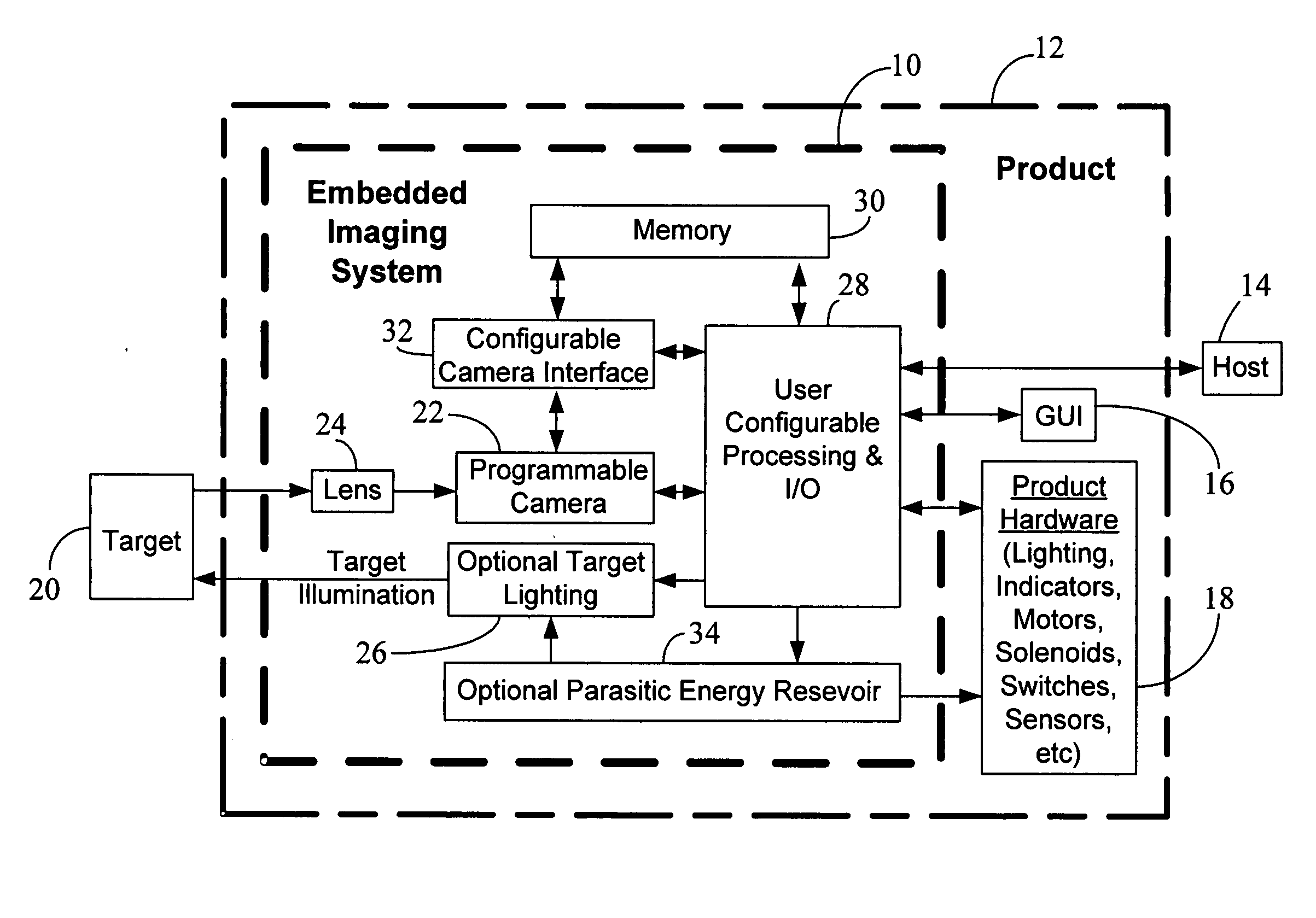
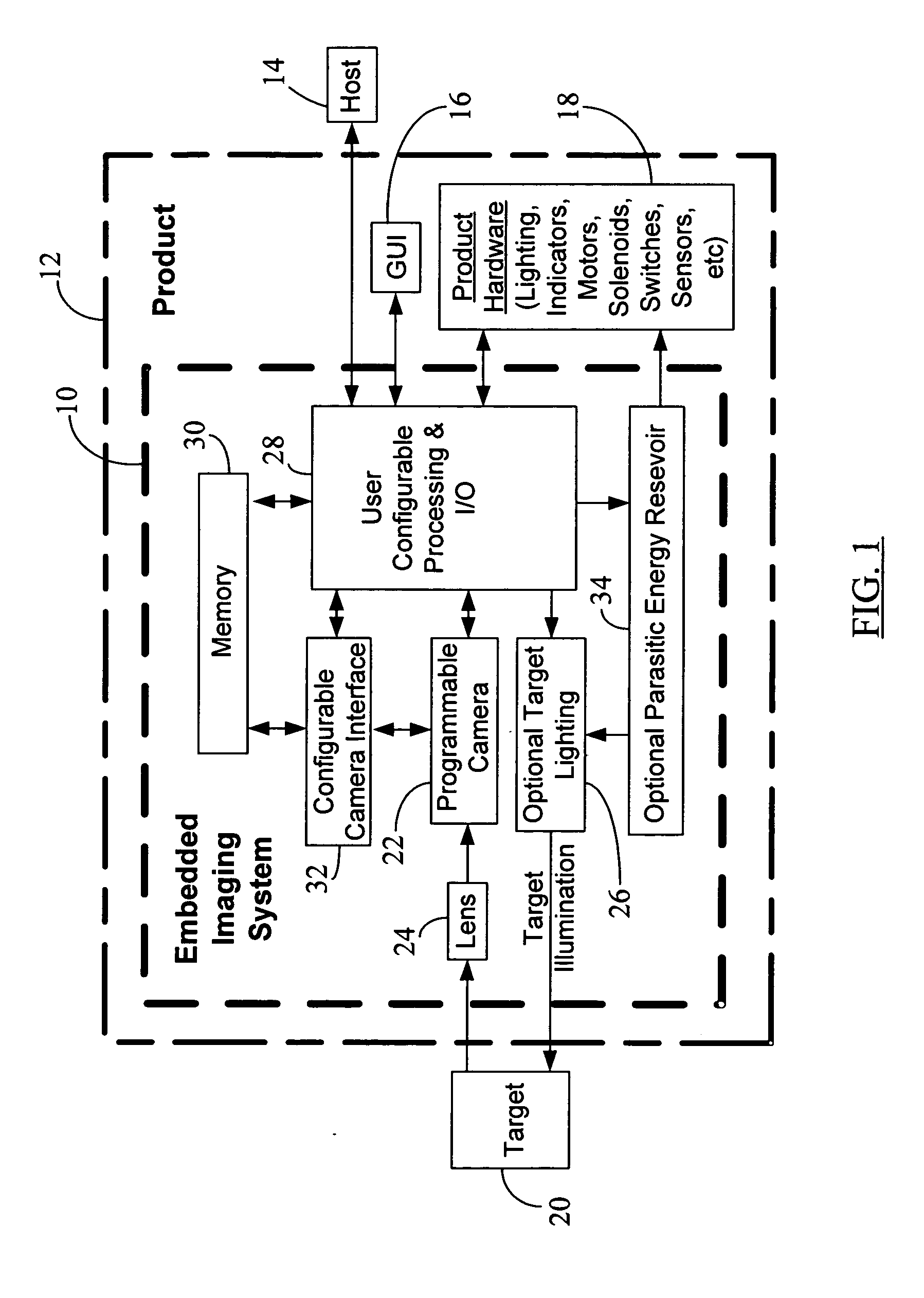
[0032]FIG. 1 shows a high level block diagram of an exemplary embodiment of an embedded sensor or imaging system 10 according to the present disclosure. The imaging system 10 is shown embedded in a typical generic product or unit 12. In this embodiment, the system 10 is doing more than taking images and handling image processing as ...


PUM


Abstract

A stand alone imaging system is disclosed that captures undistorted, high resolution, stop-action images of objects (e.g., medicine pills) moving at automation speeds, processes the images in real time, and then performs real-time I/O based control that is a function of the image processing results. The imaging system has a form factor that enables it to be embedded inside a product (e.g., a pill dispenser). The imaging system also has a flexible I/O system so that a variety of different applications can be handled by changing only the programming and the external hardware connected to the device in which the imaging system is embedded. In the case of pill dispensing and quality control, a miniature, low cost imaging system can be embedded in a pill dispenser to obtain a pill image and then process the image in real time as the pill moves through a counting system. The embedded imaging system processes the images fast enough and with sufficient quality and resolution so as to command a pill counting mechanism to dispense or reject the pill based on the image processing results. Images of the pills can also be sent to a remote location or an archive. The embedded imaging system has sufficient processing power and I/O to control the entire pill counting mechanism. Lighting may be provided by a separate solid state lighting source which may be controlled by the embedded imaging system's camera or operated independently. Because of the rules governing abstracts, this abstract should not be used to construe the claims.

Description

BACKGROUND [0001] 1. Field of the Disclosure [0002] The present disclosure generally relates to imaging systems and, more particularly, to a system and method to perform imaging and control using an embedded imaging system. [0003] 2. Brief Description of Related Art [0004] There are many types of automated equipment that count and dispense pharmaceutical pills in pharmacies, hospitals and central fill facilities for end use. These types of pill counting and dispensing machines use thru-beam optical sensors to count pills as they are dispensed. Some of the machines also make crude attempts to detect pill fragmentation using multiple thru-beam optical sensors. [0005] Pharmaceutical companies sometimes use vision-based applications to examine pills and make decisions about pill quality. However, the vision-based inspection requirements of a pharmaceutical production facility are significantly different from those of a retail pill counting and dispensing machine that would be used in a ...

Claims


Application Information

Patent Timeline
Patent Type & Authority Applications(United States)
IPC IPC(8): G06K9/00G06V20/66
CPCG06T7/001G06T2207/30164G06V20/66G06F18/00
Inventor POPOVICH, JOSEPH JR.VOLKAR, JOHNREMLS, STEVEN J.TOOLE, WILLIAM
Owner PARATA SYST
Why Eureka
Try Eureka