Energy regeneration system for working machinery

a technology for working machinery and energy regeneration, which is applied in the direction of fluid couplings, servomotors, couplings, etc., can solve the problems of large energy storage capacity, short energy storage time, and poor energy regeneration efficiency

Inactive Publication Date: 2006-05-04
CATEPILLAR SARL +1
View PDF12 Cites 42 Cited by
  • Summary
  • Abstract
  • Description
  • Claims
  • Application Information

AI Technical Summary

Benefits of technology

[0009] In another aspect, the present disclosure provides a work machine. The work machine includes an engine, and a hydraulic system which includes a hydraulic pump, a hydraulic actuator coupled with the hydraulic pump and having first and second supply/discharge ports, and a discharge flow line from the hydraulic actuator. The work machine further includes a variable displacement hydraulic motor fluidly disposed between the first and second supply/d

Problems solved by technology

However, in accordance with techniques including a regeneration circuit, although part of the discharge oil from the head side oil chamber of the hydraulic cylinder can be regenerated, much of the oil is diverted into an oil tank directly, as a result of a problem in poor energy regeneration efficiency.
Meanwhile, the technique including the accumulator can require a large energy s

Method used


Image

  • Energy regeneration system for working machinery
  • Energy regeneration system for working machinery
  • Energy regeneration system for working machinery

Examples


second embodiment

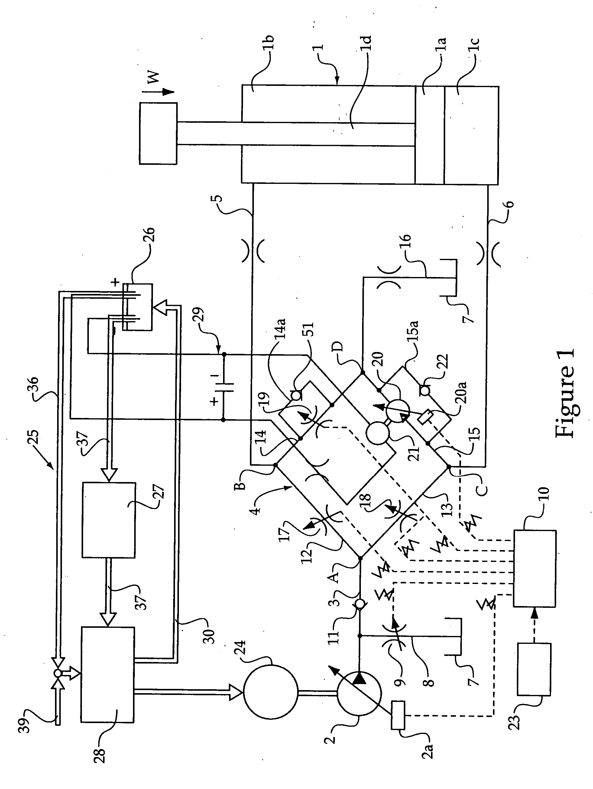
[0032] First, in respect to the second embodiment shown in FIG. 2, the fuel cell device 25 comprises a reformer 31 for generating hydrogen using chemical fuel such as methanol, ethanol, or LPG as a raw material, where the hydrogen generated by the reformer 31 is merged into hydrogen from the above-mentioned hydrogen storage device 27 to be supplied to the fuel cell 28. Thus providing the reformer 31 allows hydrogen to be supplied to the fuel cell 28 in full measure without increasing the size of the hydrogen storage device 27.

third embodiment

[0033] Also, in the third embodiment shown in FIG. 3, no fuel cell device is provided, but a capacitor 32 and an storage battery 33 for storing electric power generated by the generator 21, and an inverter 34 for converting DC power supplied from the storage battery 33 into AC power and for controlling the voltage is provided, where the motor 24 is adapted to be driven by electric power supplied from the inverter 34.

[0034] Further, in the first to third embodiments, the motor 24 is used as a power source for driving the hydraulic pump 2. In the case of working machinery including a plurality of hydraulic actuators such as a construction machine, however, where regeneration energy of discharge oil from the hydraulic cylinder 1 runs short of power, or the size of a power storage device such as a storage battery may possibly be increased as large as it is difficult to be mounted on the working machine. Hence, in the fourth embodiment shown in FIG. 4, an engine 35 is mounted as a power ...

first embodiment

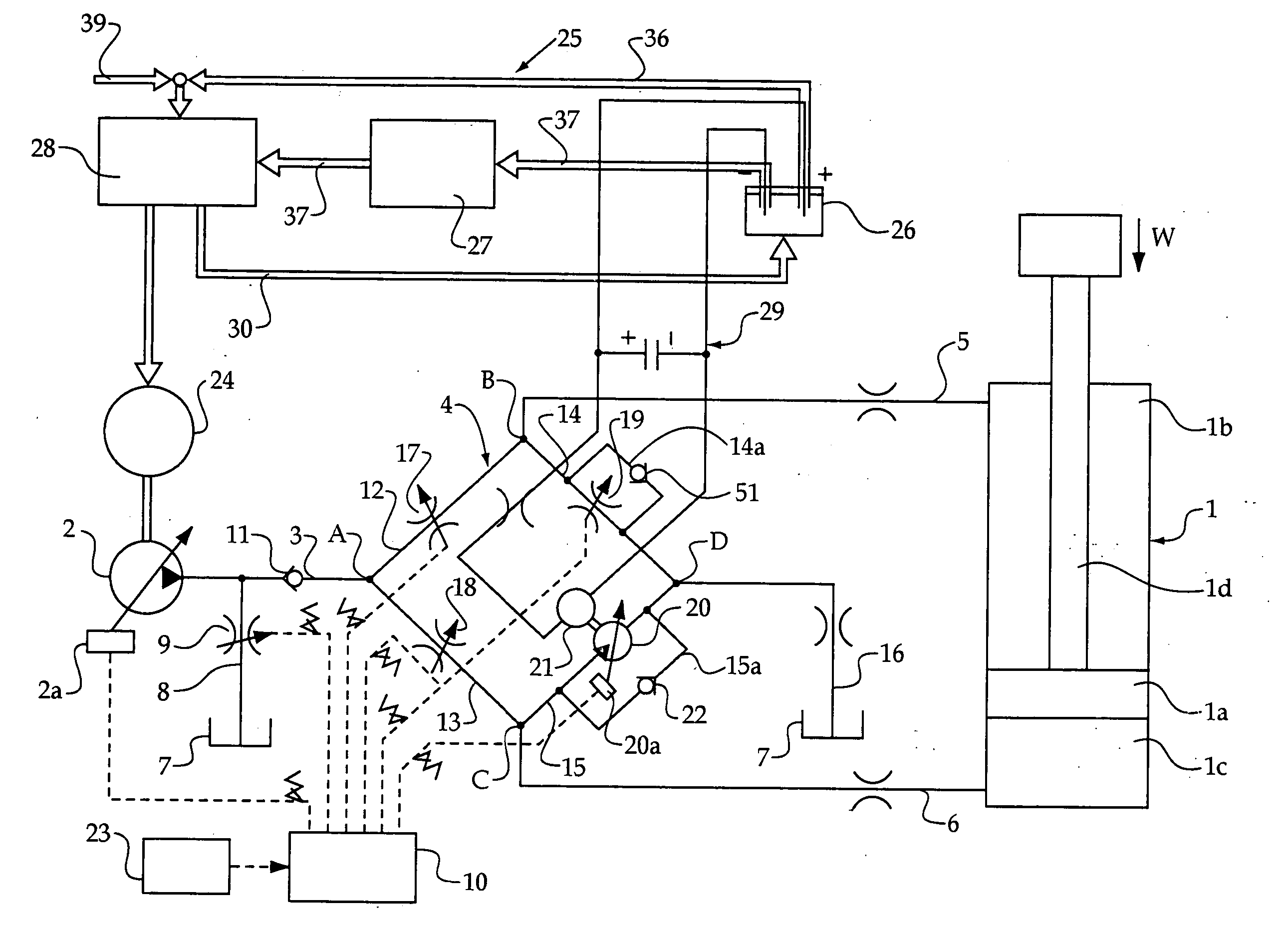
[0035] In the first embodiment as arranged above, when compressing the hydraulic cylinder 1, pressure oil is to be supplied to the rod side oil chamber 1b while oil is to be discharged from the head side oil chamber 1c. For the reason that the discharge oil from the head side oil chamber 1c has high pressure due to the application of the weight load W and that the pressure receiving area of the piston 1a facing the head side oil chamber 1c is larger than that of the piston 1a facing the rod side oil chamber 1b by the cross-sectional area of the rod 1d, a larger amount of oil than that of pressure oil supplied to the rod side oil chamber 1b is to be discharged from the head side oil chamber 1c. Then, part of the discharged oil from the head side oil chamber 1c is supplied to the rod side oil chamber 1b as regeneration oil, as mentioned above, through the head side line 6, the second flow rate control line 13, the first flow rate control line 12, and the rod side line 5, while the res...


PUM


Abstract

A method and apparatus to improve regeneration efficiency when regenerating the energy of discharge fluid from a fluid pressure actuator as electrical energy. In a flow rate control line 15, which finctions as a discharge flow path for oil discharged from a head side oil chamber 1c of a hydraulic cylinder 1, is provided a displacement variable regenerating hydraulic motor 20, where controlling the displacement of the regenerating hydraulic motor 20 allows the flow rate of discharge oil from the hydraulic cylinder head side oil chamber 1c to be controlled. A generator 21, which generates electric power due to the rotation of the regenerating hydraulic motor 20, is further provided.

Description

CROSS-REFERENCE TO RELATED APPLICATIONS [0001] This application is a continuation-in-part of U.S. patent application Ser. No. 10 / 714171, filed Nov. 14, 2003.TECHNICAL FIELD [0002] The present disclosure relates to a technical field of an energy regeneration system for working machinery comprising a fluid pressure actuator, in which the energy of fluid discharged from the fluid pressure actuator is regenerated. BACKGROUND [0003] In general, working machinery such as hydraulic excavators are provided with various kinds of fluid pressure actuators which are operated by pressurized fluid from pumps. There have conventionally been known techniques for regenerating the energy of fluid discharged from the fluid pressure actuators such as, in the case that the fluid pressure actuators are hydraulic cylinders, a technique in which is provided a regeneration circuit for supplying part of the oil discharged from a head side oil chamber of each hydraulic cylinder to a rod side oil chamber. In a...

Claims


Application Information

Patent Timeline
IPC IPC(8): F16D31/02E02F9/22F15B11/00F15B21/14
CPCE02F9/2207E02F9/2217E02F9/2296F15B11/006F15B21/14F15B2211/20515F15B2211/20546F15B2211/26F15B2211/30575F15B2211/31576F15B2211/327F15B2211/45F15B2211/63F15B2211/6346F15B2211/6651F15B2211/7053F15B2211/88
Inventor YOSHINO, KAZUNORI
Owner CATEPILLAR SARL
Why Eureka
Try Eureka