Steering system and method of control

a steering system and steering motor technology, applied in the direction of fluid steering, electric steering, vehicle components, etc., can solve the problems of increasing the load on the steering motor and promoting the generation of heat in the steering motor, so as to reduce the load applied to the steering actuator, suppress the excessively quick steering of the driver, and increase the reaction force

Inactive Publication Date: 2006-05-04
HONDA MOTOR CO LTD
View PDF5 Cites 25 Cited by
  • Summary
  • Abstract
  • Description
  • Claims
  • Application Information

AI Technical Summary

Benefits of technology

[0010] The present invention was made to provide a steering system which can suppress the increase in the temperature of a steering system in an ensured fashion.
[0021] By adopting the above configuration, the load applied to the steering actuator can be reduced by reducing a ratio of the rotating angle to a steering input. In addition, excessively quick steering by the driver can be suppressed by increasing the reaction force imparted to the operating element, and as a result, the increase in the load applied to the steering actuator can be suppressed.
[0025] By adopting the above configuration, the steering effort inputted to the operating element by the driver can be utilized as a drive force which steers the drive road-wheels about their swivel pins by bringing the connecting unit into engagement, and as a result, the load applied to the steering actuator can be reduced.
[0030] According to the first aspect of the invention, since the load applied to the steering actuator can be reduced by reducing the ratio of the rotating angle to the steering input, and additionally, excessively quick steering by the driver can be suppressed by increasing the reaction force imparted to the operating element, the increase in the load applied to the steering actuator can be suppressed, and the increase in the temperatures of the steering actuator and the constituent member involved therein can be prevented, thereby making it possible to eliminate the generation of a drawback attributed to heat that would otherwise be generated.
[0031] According to the second aspect of the invention, since the load applied to the steering actuator can be reduced by bringing the connection unit into engagement, the increase in the temperatures of the steering actuator and the constituent member involved therein can be prevented, thereby making it possible to eliminate the generation of a drawback attributed to heat that would otherwise be generated.

Problems solved by technology

However, when the supply of power to the reaction motor is reduced when the temperature of the reaction motor reaches or exceeds the predetermined temperature as described the JP-A-2004-194385, while the increase in the temperature of the reaction motor can be suppressed, since the reaction force is reduced, the driver is then allowed to increase the steering input to the operating element with ease, and as a result, the load to the steering motor is increased, causing a problem that the generation of heat in the steering motor is promoted.

Method used


Image

  • Steering system and method of control
  • Steering system and method of control
  • Steering system and method of control

Examples


Embodiment Construction

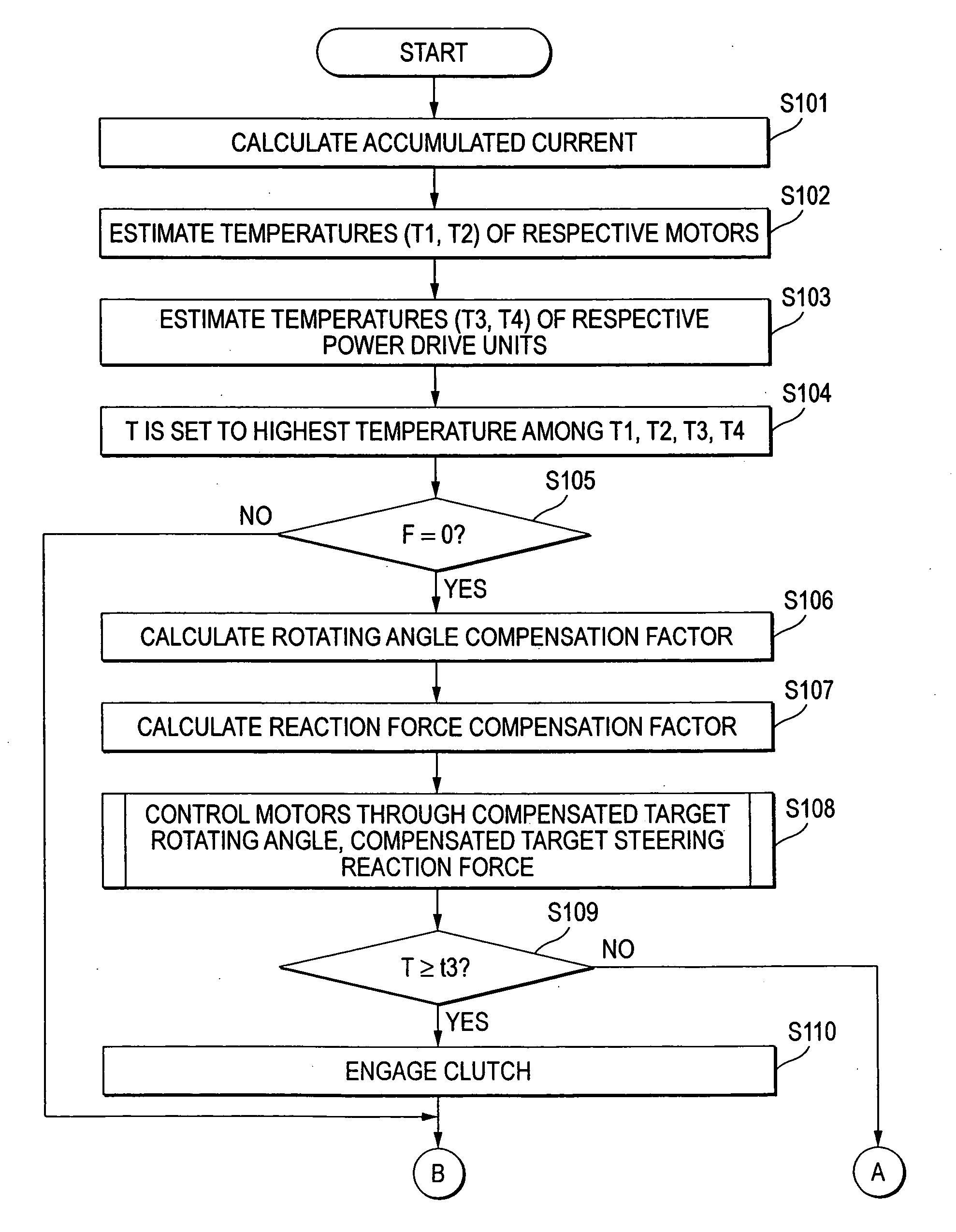
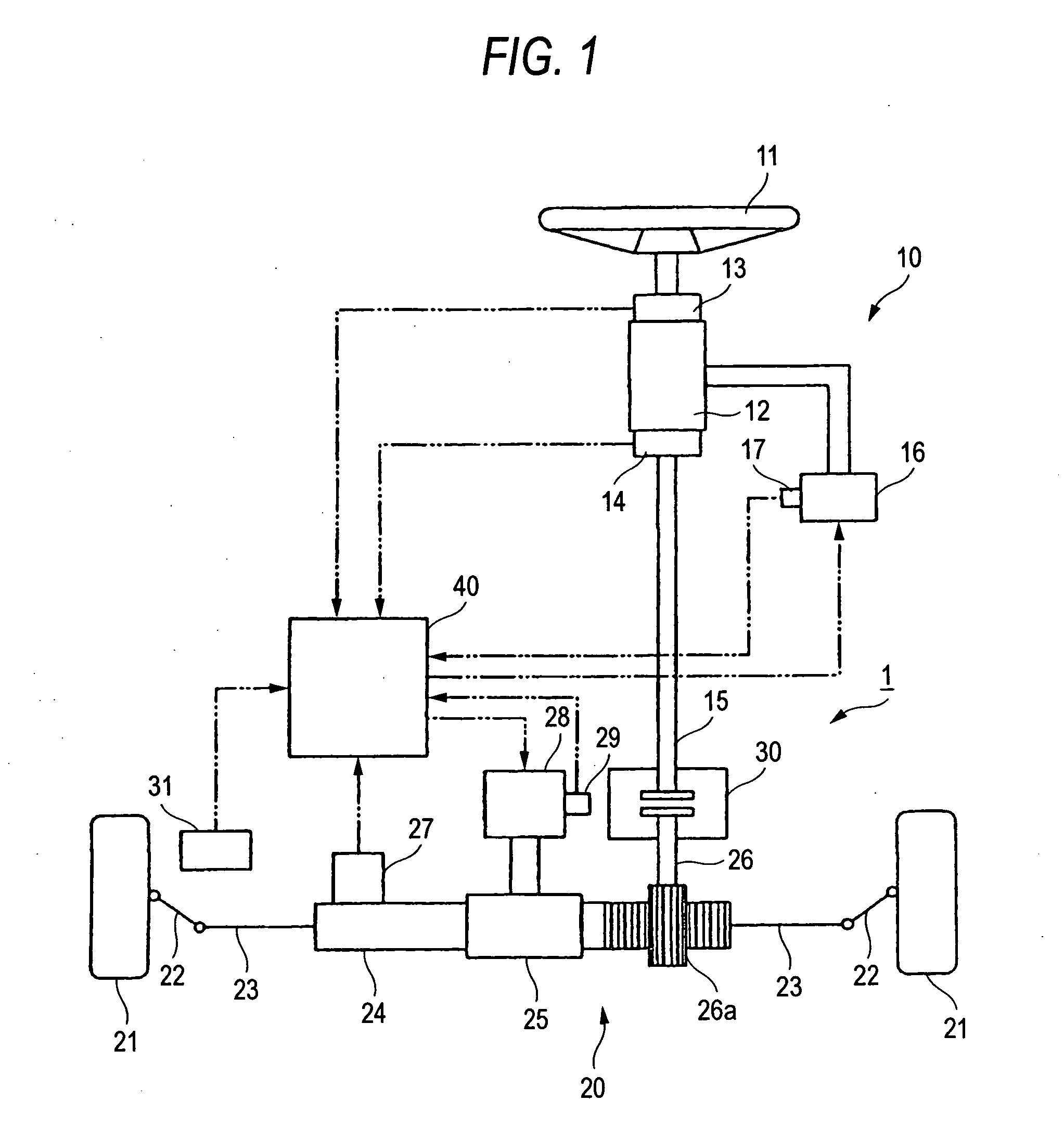
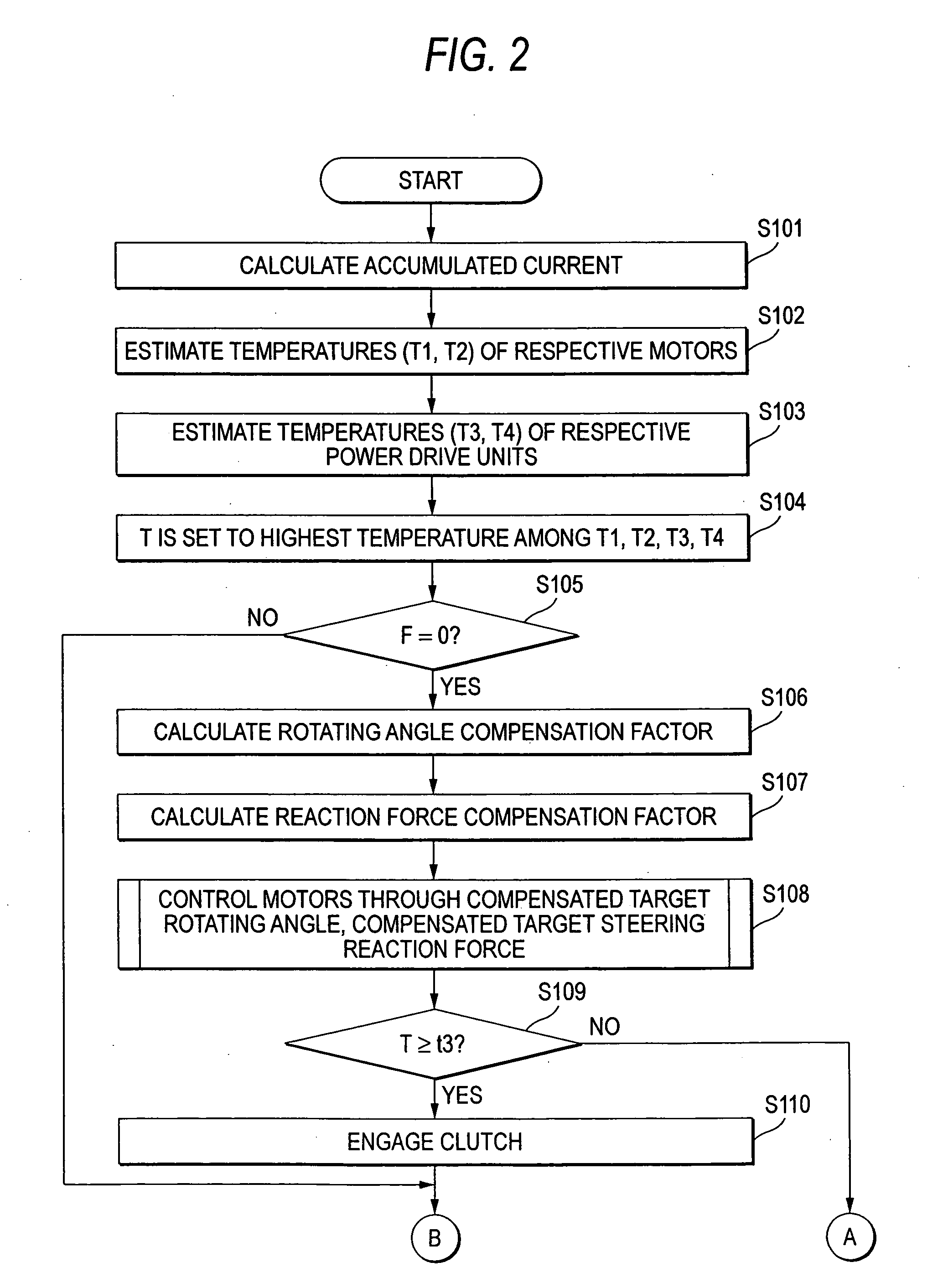
[0037] An embodiment of a steering system according to the invention will be described below by reference to FIGS. 1 to 5.

[0038] As shown in FIG. 1, an SBW type steering system 1 includes a steering input unit (a steering unit) 10 and a steering output unit (a steering unit) 20 which steers steered road-wheels, and the steering input unit 10 and the steering output unit 20 are made to be mechanically connected to and disconnected from each other via a clutch unit 30. In addition, the steering output unit 20 is electrically controlled by a steering electronic control unit (ECU) 40 based on a steering input to the steering input unit 10.

[0039] The steering input unit 10 is made up of a steering wheel 11 that is operated by a driver, a reaction motor 12 which imparts a reaction torque to the steering wheel 11, a steering angle sensor 13 which detects a steering angle of the steering wheel 11 and outputs an electric signal corresponding to the steering angle so detected to the ECU 40,...


PUM


Abstract

A steering system includes a steering wheel, a steering angle sensor detecting a steering angle, a steering motor steering road-wheels, a reaction motor imparting a reaction force to the steering wheel, an ECU driving the steering motor with respect to a detected steering angle and a temperature detecting unit detecting temperatures of the steering motor, the reaction motor or a constituent member involved in the temperatures of the motors. When the temperature detected is larger than a predetermined value, the ECU performs such that a ratio of the rotating angle to the steering angle is made smaller than one that is to result when the temperature is equal to or smaller than the predetermined value, or a reaction force that is to be imparted to the steering wheel is made larger.

Description

[0001] The present invention claims foreign priority under 35 USC 119 based on Japanese patent application No. P. 2004-319289, filed on Nov. 2, 2004, the content of which is incorporated herein by reference. BACKGROUND OF THE INVENTION [0002] 1. Field of the Invention [0003] The present invention relates to a steering system, in which an operating element that is to be operated by a driver, is not mechanically connected to steered road-wheels to be steered or rotated to steer a vehicle. [0004] 2. Description of the Background Art [0005] In a so-called SBW (steer-by-wire) type steering system in which a steering wheel (an operating element) that is to be operated by the driver, and steered road-wheels are not mechanically connected to each other, the steered road-wheels are turned by a steering motor and a reaction force is imparted to the operating element by a reaction motor. These motors are controlled independently, whereby a ratio of a rotating angle of the steered road-wheels t...

Claims


Application Information

Patent Timeline
Patent Type & Authority Applications(United States)
IPC IPC(8): B62D5/04
CPCB62D5/003B62D5/006B62D5/0496
Inventor SUGITANI, NOBUOAKUTA, YOSHIMITSUASAUMI, HISAOIWAI, HITOSHIKAWANO, MASAAKINISHIMORI, TAKASHI
Owner HONDA MOTOR CO LTD
Why Eureka
Try Eureka