Plasma spray apparatus

Inactive Publication Date: 2006-05-04
UNITED TECH CORP
View PDF35 Cites 34 Cited by
  • Summary
  • Abstract
  • Description
  • Claims
  • Application Information

AI Technical Summary

Problems solved by technology

Prior art methods and apparatus required masking the workpiece and applying the coating in dedicated facilities because the

Method used


Image

  • Plasma spray apparatus
  • Plasma spray apparatus
  • Plasma spray apparatus

Examples


Embodiment Construction

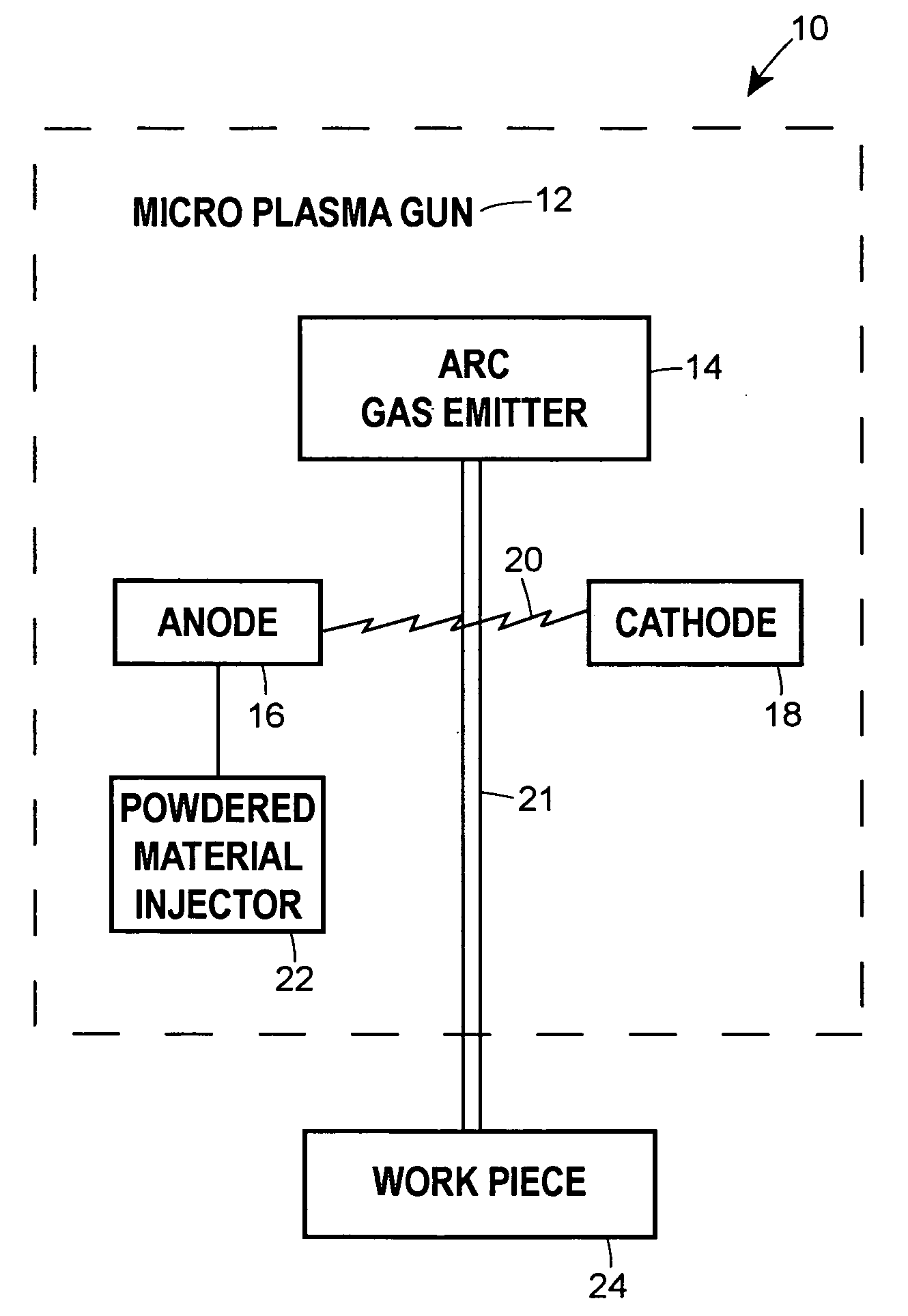
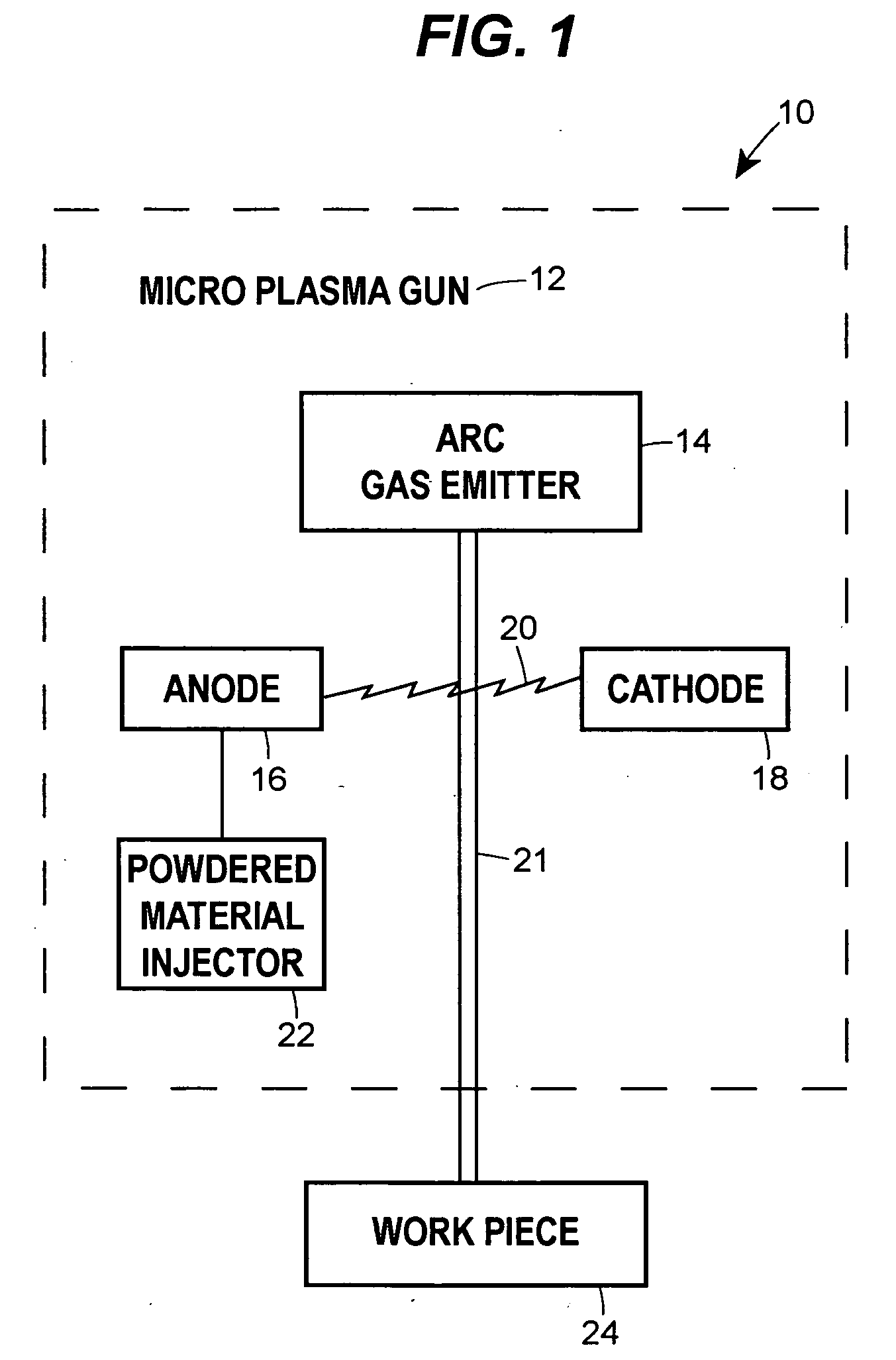
[0014] Referring now to FIG. 1, one embodiment of a plasma spray apparatus 10 schematically represented by the dashed box outline is depicted. In generalized terms, the plasma spray apparatus 10 includes a plasma gun 12 having an arc gas emitter 14, an anode 16, and a cathode 18. An electric arc 20 is generated between the anode 16 and cathode 18. A plasma stream 21 is formed when arc gas is injected from the arc gas emitter 14 and passes through the arc 20. A powdered material injector 22 dispenses powdered material into the plasma stream which transports the powdered material to the workpiece 24 to form a coating thereon. The size of the plasma stream 21 created by the device and / or the power used by the device determines whether the device is considered a microplasma spray apparatus. When the plasma stream 21 is small and / or the power used by the device is low, the device is considered a microplasma spray device. FIG. 1 displays a microplasma spray device.

[0015] For example, the...


PUM

PropertyMeasurementUnit
Fractionaaaaaaaaaa
Fractionaaaaaaaaaa
Angleaaaaaaaaaa

Abstract

A microplasma spray coating apparatus includes a microplasma apparatus with an anode, cathode, and an arc generator for generating an electric arc between the anode and cathode. An arc gas emitter injects inert gas through the electric arc. The electric arc is operable for ionizing the gas to create a plasma gas stream. A powder injector nozzle extends through the anode and injects powdered material into the plasma stream for transfer to the workpiece.

Description

FIELD OF THE INVENTION [0001] The present disclosure generally relates to a plasma spray coating apparatus, such as a microplasma spray coating apparatus, for spray coating a workpiece and a method for using the same. BACKGROUND OF THE DISCLOSURE [0002] Plasma coating methods and apparatus are known. For example, one such method and apparatus for plasma flame spray coating material onto a substrate by means of passing a plasma forming gas through a nozzle electrode, and passing an arc forming current between the nozzle electrode and a rear electrode to form a plasma effluent. The method includes introducing coating material into the plasma effluent, passing the plasma effluent axially through a wall shroud extending from the exit of said nozzle electrode, and forming a flame shroud for the plasma effluent. The coating is thereby applied to the substrate. [0003] One area where such technology is particularly advantageous is in connection with coating various components, particularly ...

Claims


Application Information

Patent Timeline
IPC IPC(8): B23K9/00B23K9/02
CPCB23K10/027C23C4/127H05H1/42C23C4/134
Inventor BLANKENSHIP, DONNZAJCHOWSKI, PAUL H.SHUBERT, GARY C.
Owner UNITED TECH CORP
Why Eureka
Try Eureka