Image pickup lens

a pickup element and image technology, applied in the field of image pickup elements, can solve the problems of more than 3 million pixels, difficult to enhance the image forming capability of a downsized low cost, and difficult to downsize an image pickup element having a high image forming capability at low cost, so as to achieve high moldability, reduce cost, and improve the effect of mass production and manufacturing cos

Inactive Publication Date: 2006-05-04
SONY CORP +1
View PDF5 Cites 11 Cited by
  • Summary
  • Abstract
  • Description
  • Claims
  • Application Information

AI Technical Summary

Benefits of technology

[0012] An image pickup lens according to the invention as described above is advantageous in terms of mass production and manufacturing cost because the second and fourth lenses that are aspherical lenses can be molded and processed by using resin that is a highly moldable and less costly material.
[0013] An image pickup lens according to the invention can suppress the chromatic aberration and improve the image forming capability by forming the first and third lenses from glass that is less light dispersing. Additionally, an image pickup lens according to the invention is advantageous in terms of mass production and manufacturing cost because the first and third lenses are spherical lenses.
[0014] Thus, in an image pickup lens according to the invention, the first and third lenses are realized as lenses that can suppress the chromatic aberration and show a high image forming capability. Additionally, the second and fourth lenses that are aspherical lenses are provided with an excellent aberration correcting function so that it is possible to provide a high performance lens in terms of image forming capability that matches small image pickup elements having a large number of pixels.
[0015] Furthermore, in an image pickup lens according to the invention, the first lens that has an image forming capability can be made thin to show a small volume because an optical aperture is arranged between the object and the first lens. Therefore, if the first lens is made of expensive glass to make it show a high performance, the image pickup lens can be further downsized and prepared at low cost.

Problems solved by technology

However, there arises a problem of tradeoff that it is difficult to enhance the image forming capability of a downsized low cost image pickup lens whereas it is difficult to downsize an image pickup element having a high image forming capability at low cost.
However, when a triplet type image pickup lens is prepared by using less costly synthetic resin, there arises a problem that it cannot accurately form an image on an image pickup element having a large number of pixels, or more than 3 million pixels to be more specific.
When the number of lenses of the image pickup lens is increased simply to improve the image forming capability, the image pickup lens comes to show a large thickness as a whole to make it impossible to meet the request of downsizing.

Method used


Image

  • Image pickup lens
  • Image pickup lens
  • Image pickup lens

Examples


example 1

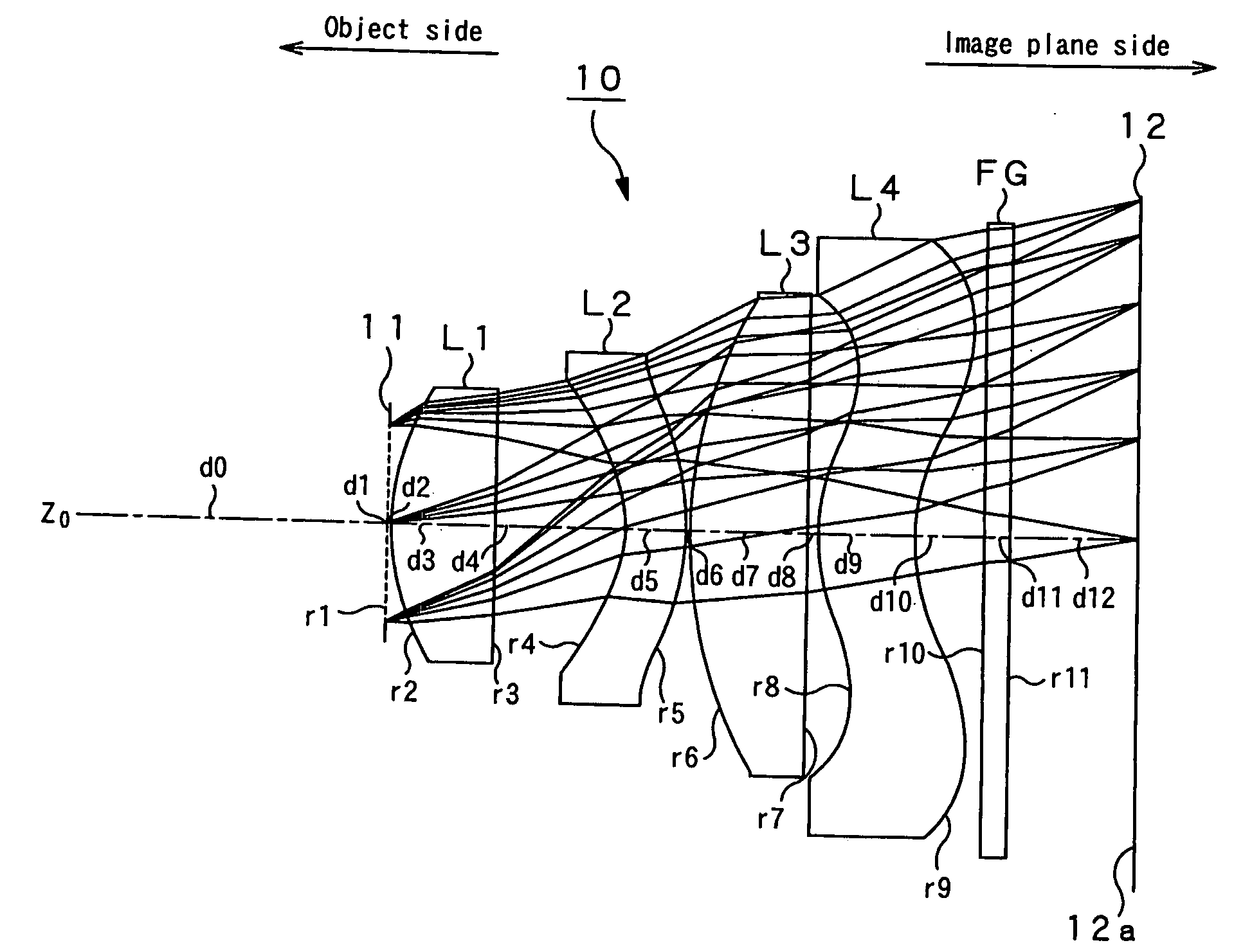
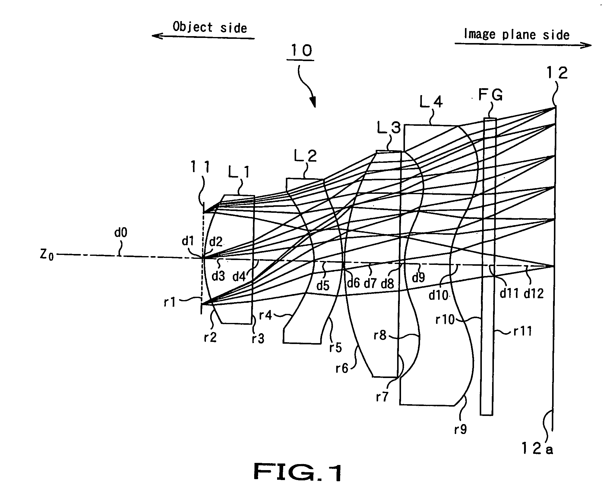
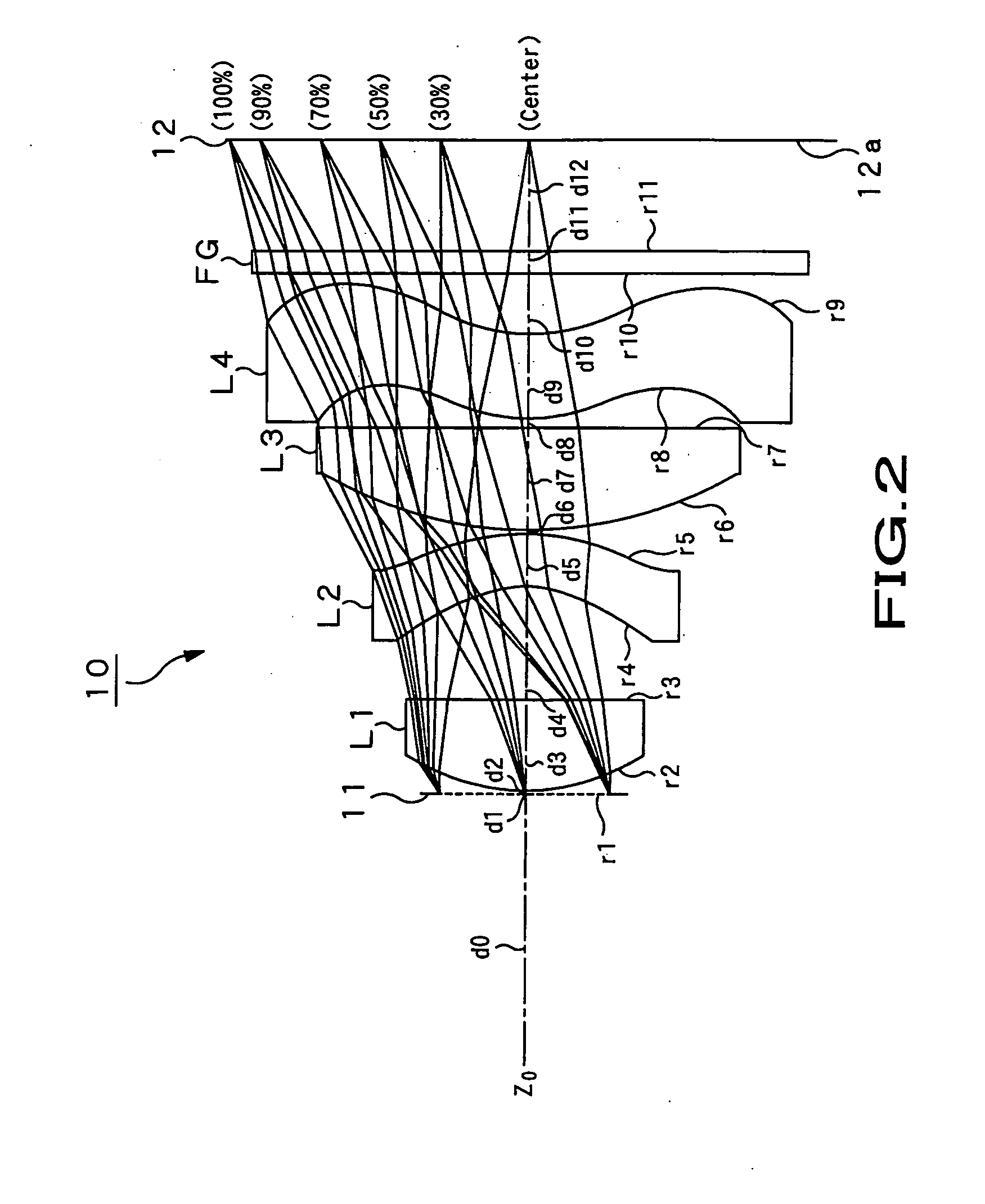
[0068]FIG. 2 illustrates the image pickup lens 10 of Example 1. In FIG. 2, incident light fluxes that strike the image pickup lens 10 respectively at the center position (0.00 mm), at 30% image height position (1.05 mm), at 50% image height position (1.75 mm), at 70% image height position (2.45 mm), at 90% image height position (3.15 mm) and at 100% image height position (3.50 mm) are shown. Some of the design data of the image pickup lens 10 of Example 1 in FIG. 2 are shown in Table 2 below.

TABLE 2f = 5.74 mm FNo = 2.8 ω = 31.3°radius ofaxial inter-surfacesurface No.curvaturedistancefocalAbbe numberiRddistance fνd0∞20661∞2.05022.4502.85.8495.03∞2.84−1.451  3.0075−2.690  3.56165.0944.87110.2281.67∞5.00381.6545.01291.4666.13510 ∞6.37711 ∞6.46012(IMG)∞7.015

[0069] As shown in Table 2, the focal distance f of the entire optical system of the image pickup lens 10 of Example 1 is 5.74 mm and the F number FNo is 2.8, while the half view angle ω is 31.3°. It is also shown in FIG. 2 that t...

example 2

[0084]FIG. 9 illustrates the image pickup lens 10 of Example 2. In FIG. 9, incident light fluxes that strike the image pickup lens 10 respectively at the center position (0.00 mm), at 30% image height position (1.05 mm), at 50% image height position (1.75 mm), at 70% image height position (2.45 mm), at 90% image height position (3.15 mm) and at 100% image height position (3.50 mm) are shown. Some of the design data of the image pickup lens 10 of Example 2 in FIG. 9 are shown in Table 4 below.

TABLE 4f = 5.68 mm FNo = 2.8 ω = 31.53°surfaceradius ofaxial inter-surfaceNo.curvaturedistancefocalAbbe numberiRddistance Ndνd0∞20861∞2.03022.6422.85.8695.03−62.95  2.84−1.404  3.0255−2.693  3.60964.8444.8749.7281.67∞4.96281.5844.97091.4376.14410 ∞6.38711 ∞6.47012(IMG)∞7.024

[0085] As shown in Table 4, the focal distance f of the entire optical system of the image pickup lens 10 of Example 2 is 5.68 mm and the F number FNo is 2.8, while the half view angle ω is 31.53°. It is also shown in Table...

example 3

[0100]FIG. 16 illustrates the image pickup lens 10 of Example 3. In FIG. 16, incident light fluxes that strike the image pickup lens 10 respectively at the center position (0.00 mm), at 30% image height position (1.05 mm), at 50% image height position (1.75 mm), at 70% image height position (2.45 mm), at 90% image height position (3.15 mm) and at 100% image heightposition (3.50 mm) are shown. Some of the design data of the image pickup lens 10 of Example 3 in FIG. 16 are shown in Table 6 below.

TABLE 6f = 5.54 mm FNo = 2.8 ω = 32.2°radiusaxial inter-surfacefocalsurface No.of curvaturedistancedistanceAbbe numberiRdNdνd0∞21411∞1.97922.8682.85.75481.63∞2.84−1.432  2.9615−3.029  3.54164.6864.9279.4081.67∞5.02481.5885.07791.5836.0410 ∞6.32811 ∞6.41712(IMG)∞7.011

[0101] As shown in Table 6, the focal distance f of the entire optical system of the image pickup lens 10 of Example 3 is 5.78 mm and the F number FNo is 2.8, while the half view angle ω is 32.2°. It is also shown in Table 6 that...


PUM


Abstract

An image pickup lens can form an excellent optical image on a compact image pickup element having a large number of pixels. The image pickup lens includes, sequentially from the object side, an optical aperture, a first lens made of glass and having at least a spherical surface at the object side and a positive refracting power, a second lens made of resin and having two aspherical surfaces and a negative refracting power, a third lens made of glass and having at least a spherical surface at the object side and a positive refracting power, and a fourth lens made of resin and having two aspherical surfaces and a negative refracting power.

Description

CROSS REFERENCES TO RELATED APPLICATIONS [0001] The present invention contains subject matter related to Japanese Patent Application JP 2004-314495 filed in the Japanese Patent Office on Oct. 28, 2004, the entire contents of which being incorporated herein by reference. BACKGROUND OF THE INVENTION [0002] 1. Field of the Invention [0003] The present invention relates to an image pickup lens to be used in an image pickup apparatus such as a digital still camera or a digital video camera. More particularly, it relates to an image pickup lens having four elements in four groups. [0004] 2. Description of the Related Art [0005] Image pickup elements such as CCDs (charge coupled devices) and CMOS (complementary metal oxide semiconductors) are being downsized and the number of pixels of such image pickup elements is being increased to improve the image quality due to the recent advancement of the technique of arranging pixels at a micro-pitch. [0006] Then, by turn, the image pickup lens for...

Claims


Application Information

Patent Timeline
Patent Type & Authority Applications(United States)
IPC IPC(8): G02B9/34
CPCG02B13/18G02B27/0025
Inventor ARAI, TAKEO
Owner SONY CORP
Why Eureka
Try Eureka