Radiographic equipment

a technology of radiographic equipment and equipment, applied in the direction of material analysis using wave/particle radiation, instruments, greenhouse gas reduction, etc., can solve the problems of limited technique, inability to detect benign organic materials, and low discrimination power of x-rays, so as to enhance the capability of single energy transmission technique, improve the accuracy of information obtained, and minimise scattering

Active Publication Date: 2006-05-04
COMMONWEALTH SCI & IND RES ORG
View PDF41 Cites 38 Cited by
  • Summary
  • Abstract
  • Description
  • Claims
  • Application Information

AI Technical Summary

Benefits of technology

[0022] An advantage of the present invention is that the neutrons are essentially mono-energetic. Hence it is possible to model the neutron transmission using a simple exponential relation and moreover, information is more accurately obtained which is useful for material identification.
[0023] The equipment according to at least one embodiment of the invention has the added advantage of direct measurement of transmitted neutrons and is therefore much more efficient when compared with prior art systems which measure secondary radiation such as neutron-induced gamma rays.
[0024] The radiographic equipment may utilise one or more neutron energies. In an example of a dual neutron energy technique, the radiographic equipment may utilise two tubes, one to produce substantially 14 MeV neutrons via the deuterium-tritium fusion reaction and a second to produce substantially 2.45 MeV neutrons via the deuterium-deuterium fusion reaction. The measurement of the neutron transmission at a second energy can be used to enhance the capability of the single energy transmission technique.
[0025] The source of X-rays or gamma-rays may comprise a radioisotope source such as 60Co or 137Cs with energy sufficient to substantially penetrate through the object to be imaged. The 60Co or 137CS source may have an energy of about 1 MeV although other e...

Problems solved by technology

However, X-rays provide little discriminating power between organic and inorganic elements.
Using X-rays the separation of illicit organic materials such as explosives or narcotics from commonly found, benign organic materials is not possible.
In practice the technique is limited by the very expensive and complex particle accelerator, the limited neutron source strength and low gamma-ray detection efficiency and the resulting slow scan speeds.
However it is limited by the very expensive and complex particle accelerator.
However this technique has not been used for imaging and its practical application to contraband detection has not been investigated.
Mikerov found that applications were limited by both the low detection efficiency of the 2 mm thick luminescent screen for fast neutrons and the high sensitivity of the screen to X rays produced by the neutron generator.
However the fact that the fast neutrons are slowed down (thermalised) prior to performing radiography limits the size of the object being imaged to a few cm.
No fast neutron radiography systems are commercially available that involve fast neutron detection.
The key drawback...

Method used


Image

  • Radiographic equipment
  • Radiographic equipment
  • Radiographic equipment

Examples


Embodiment Construction

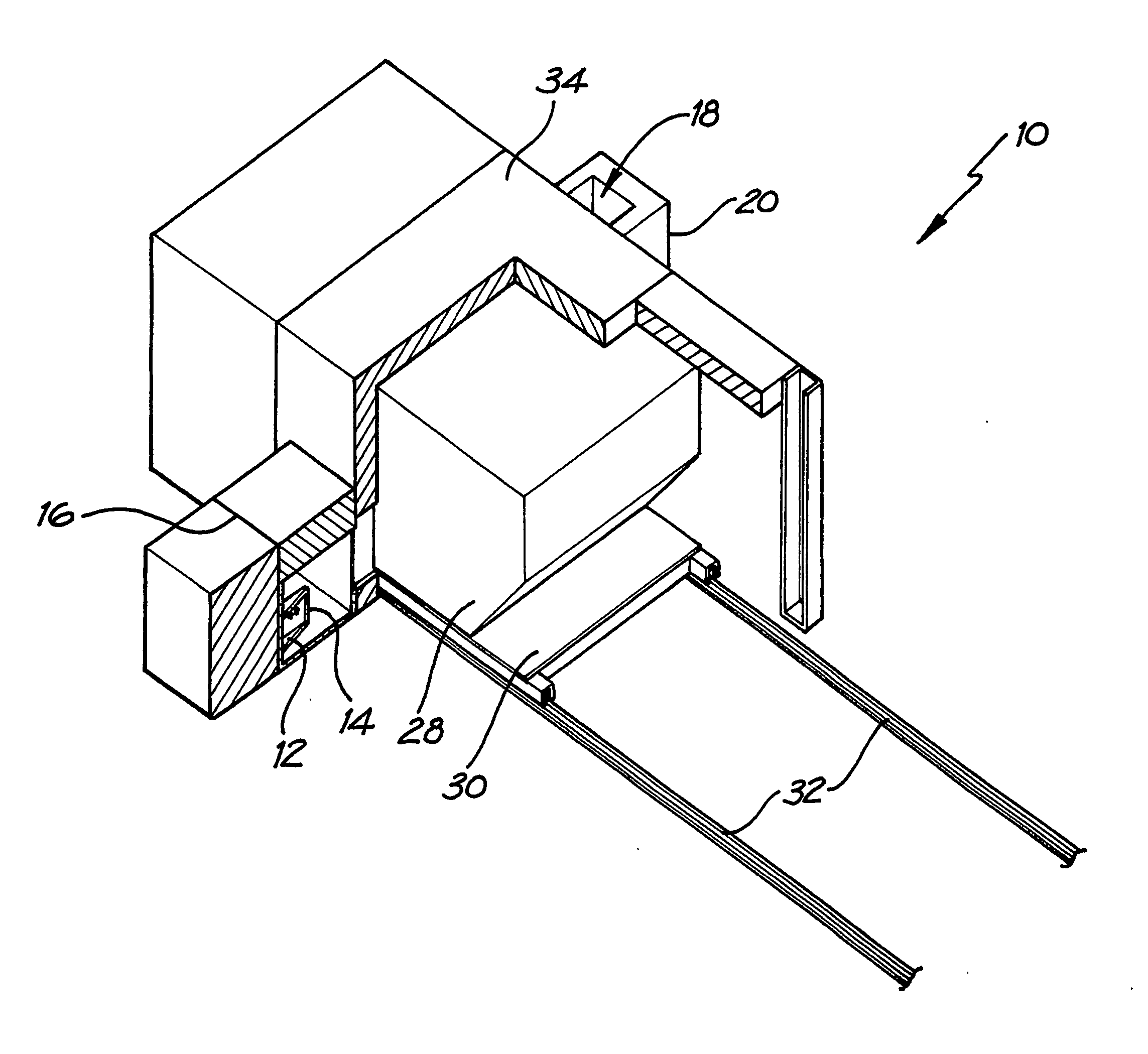
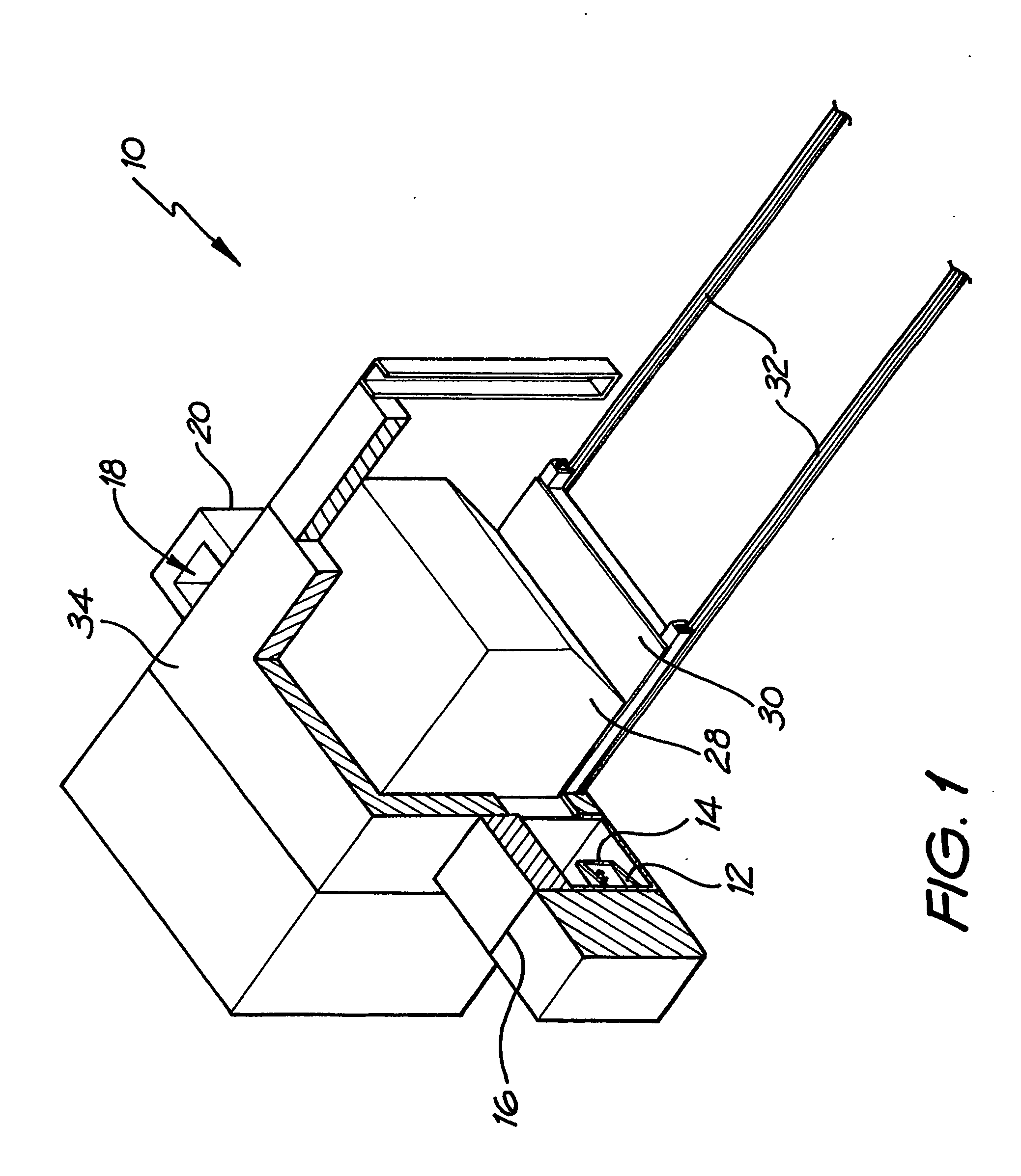
[0072]FIG. 1 illustrates the general layout of the radiographic equipment 10. The equipment 10 includes two separate generators of radiation, the first is an A-325 MF Physics neutron generator having a D-T neutron emitting module to produce a neutron energy source 12 having an energy of 14 MeV. The neutron generator is operated at a voltage of 80-110 kV. The second generator of radiation is a 0.82 GBq (or 22 mCi) 60Co source 14 to produce a source of gamma-rays and is located to the right of and adjacent to the neutron generator. The neutron generator and 60Co source 14 are situated within a source shield housing 16.

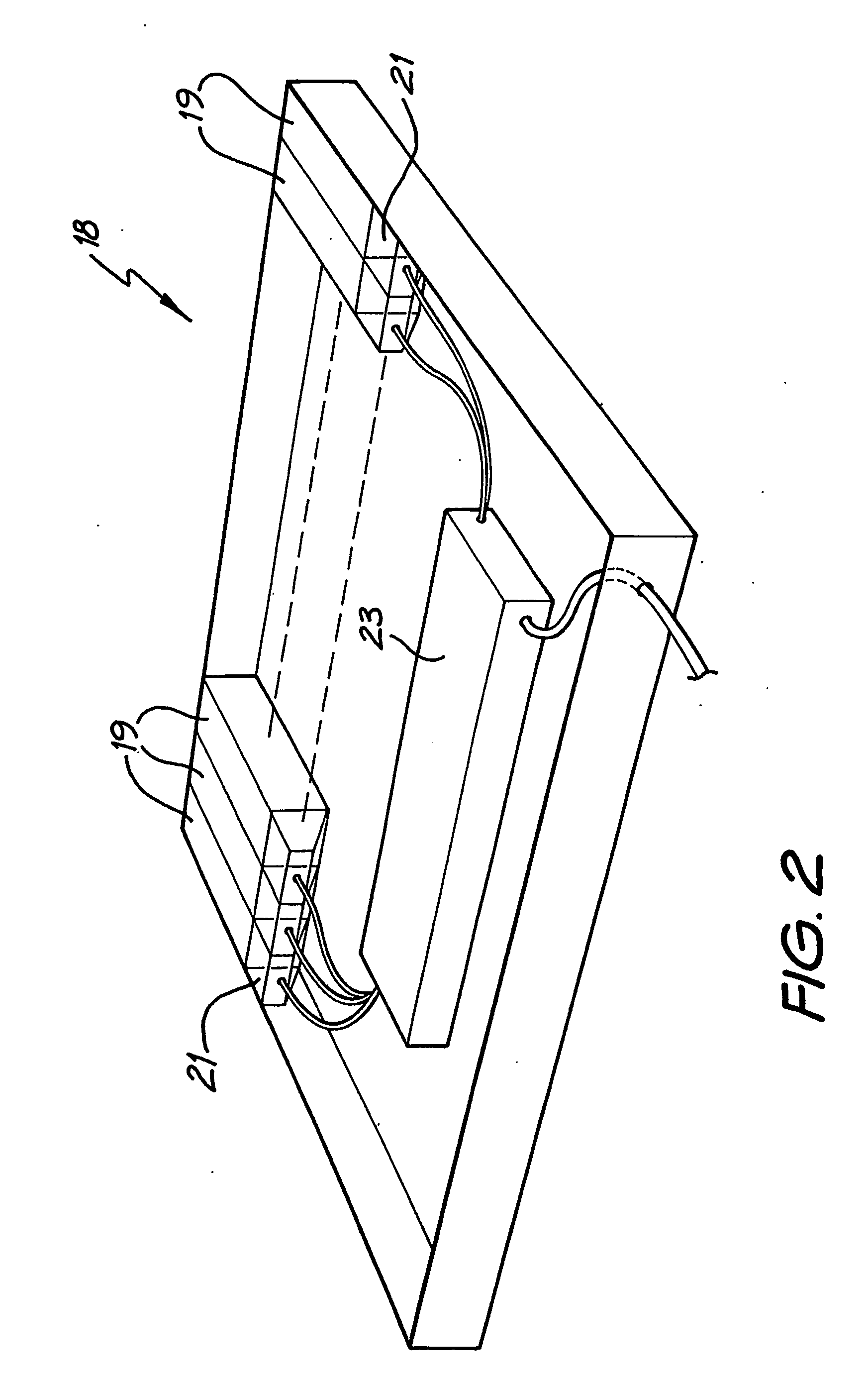
[0073] A 1600 mm long and 20 mm wide detector array 18 is situated in the vicinity of the radiation source and is housed in a detector shield housing 20. The detector array 18, more clearly shown in FIG. 2, is built up of eighty plastic scintillator rods 19 (of which only a portion are shown), each with a radiation receiving area of 20 mm×20 mm, and a length of 75 mm. T...


PUM


Abstract

The invention concerns radiographic equipment. The equipment includes a source of substantially mono-energetic fast neutrons produced via the deuterium-tritium or deuterium-deuterium fusion reactions, comprising a sealed-tube or similar generator for producing the neutrons. The equipment further includes a source of X-rays or gamma-rays of sufficient energy to substantially penetrate an object to be imaged and a collimating block surrounding the neutron and gamma-ray sources, apart from the provision of one or more slots emitting substantially fan-shaped radiation beams. Further included is a detector array comprising a multiplicity of individual scintillator pixels to receive radiation energy from the sources and convert the received energy into light pulses, the detector array aligned with the fan-shaped beams emitted from the source collimator and collimated to substantially prevent radiation other than that directly transmitted from the sources reaching the array. Conversion means are included for converting the light pulses produced in the scintillators into electrical signals. Conveying means are included for conveying an object between the sources and the detector array. Computing means are included for determining from the electrical signals the attenuation of the neutrons and the X-ray or gamma-ray beams and to generate output representing the mass distribution and composition of the object interposed between the source and detector array. The equipment further includes a display means for displaying images based on the mass distribution and the composition of the object being scanned.

Description

TECHNICAL FIELD [0001] This invention concerns radiographic equipment. In particular the invention concerns radiographic equipment for the detection of concealed articles, substances and materials. For instance, the invention may be applied to the detection of concealed weapons, explosives, contraband, drugs and other articles, substances and materials in items such as aircraft baggage, airfreight or shipping containers. BACKGROUND ART [0002] Technologies based on X-rays, gamma-rays and neutrons have been proposed to tackle this problem (Hussein, E., 1992, Gozani, T., 1997, An, J. et al, 2003). The most widely adopted technology is the X-ray scanner which forms an image of an item being examined by measuring the transmission of X-rays through the item from a source to a spatially segmented detector. X-rays are most strongly attenuated by dense, higher atomic number materials such as metals. Consequently, X-ray scanners are ideal for detecting items such as guns, knives and other wea...

Claims


Application Information

Patent Timeline
IPC IPC(8): G01N23/04G01N23/09
CPCG01N23/09G01N23/10Y02E30/10G01T1/16G01V5/00G01T3/00
Inventor SOWERBY, BRIAN DAVIDTICKER, JAMES RICHARD
Owner COMMONWEALTH SCI & IND RES ORG
Why Eureka
Try Eureka