Method and apparatus for suppressing optical surge in optical burst switching network

Inactive Publication Date: 2006-05-04
SAMSUNG ELECTRONICS CO LTD
View PDF6 Cites 9 Cited by
  • Summary
  • Abstract
  • Description
  • Claims
  • Application Information

AI Technical Summary

Benefits of technology

[0027] An aspect of the present invention provides a method for suppressing a su

Problems solved by technology

As mentioned above, the transmission of the optical circuit signal requires establishing the optical path in advance, which causes to delay the transmission time of the optical circuit signal.
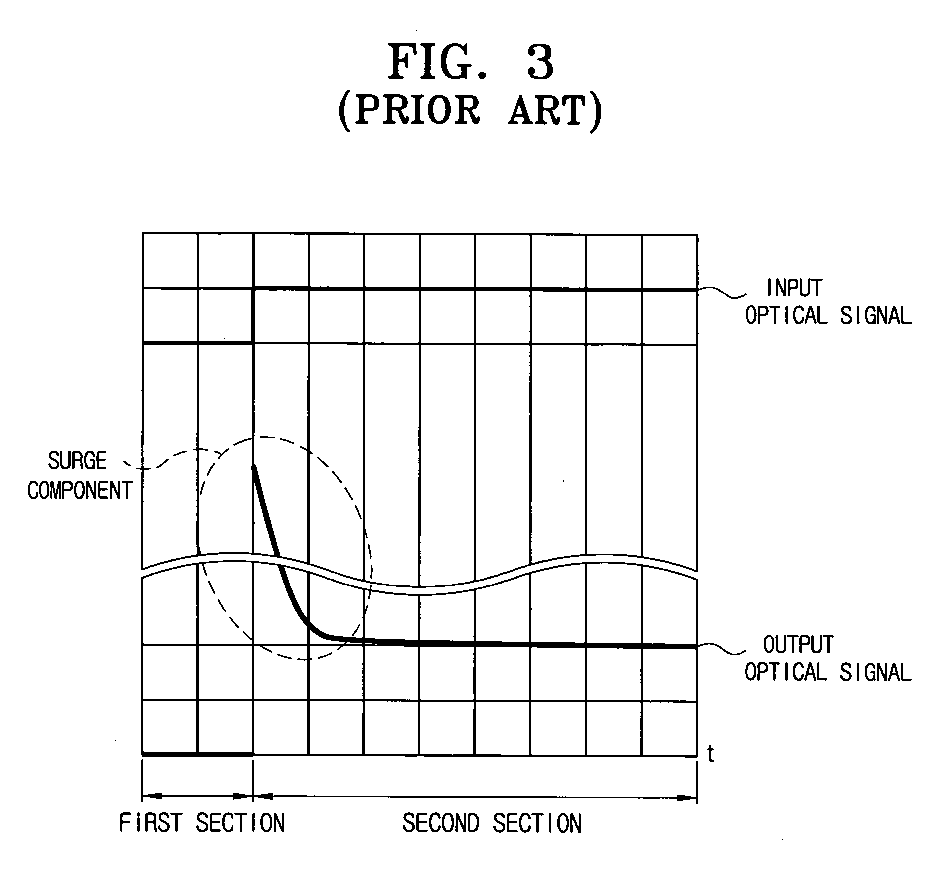
The surge component shortens the life span of devices on the optical path, and causes damage to the devices.
Fu

Method used


Image

  • Method and apparatus for suppressing optical surge in optical burst switching network
  • Method and apparatus for suppressing optical surge in optical burst switching network
  • Method and apparatus for suppressing optical surge in optical burst switching network

Examples


Embodiment Construction

[0043] Reference will now be made in detail to the exemplary embodiments of the present invention, examples of which are illustrated in the accompanying drawings, wherein like reference numerals refer to like elements throughout. The exemplary embodiments are described below to explain the present invention by referring to the figures.

[0044] Aspects of the present invention provide a method for suppressing a surge component that occurs at an optical amplifier.

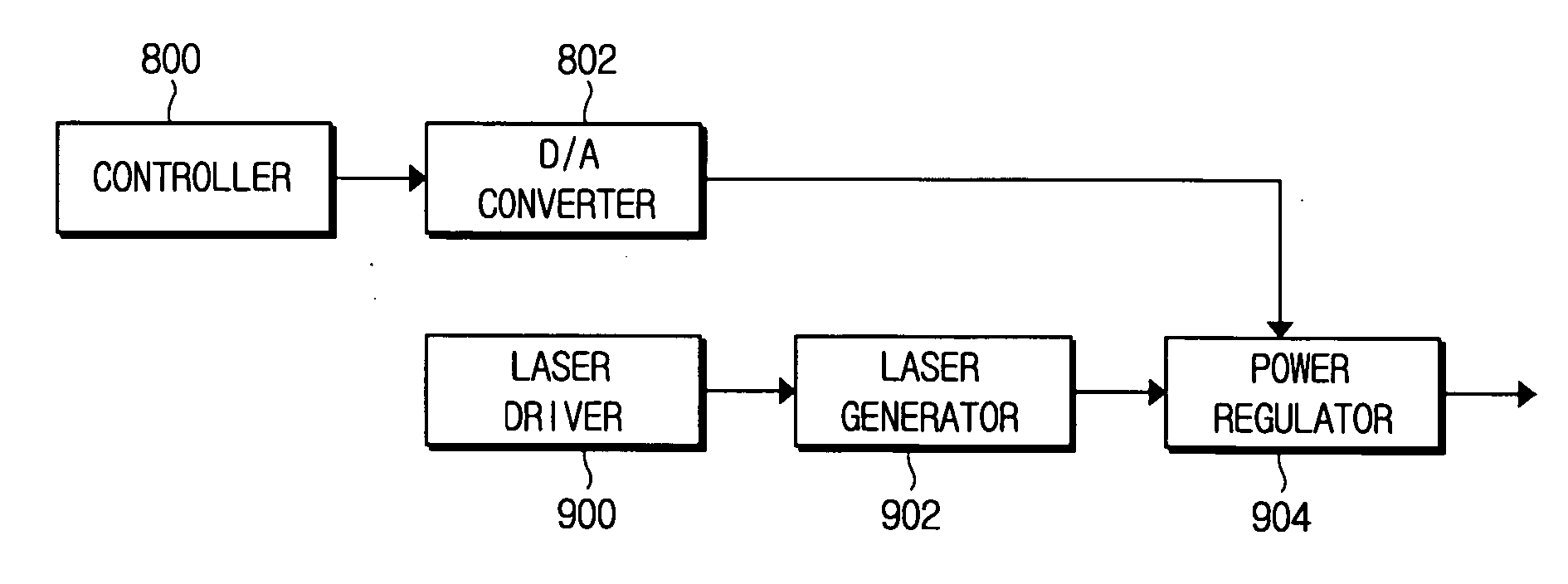
[0045]FIG. 6 depicts a node for suppressing a surge component occurring at an optical amplifier, and an optical path according to an exemplary embodiment of the present invention. Node 602 includes a surge component suppressor 600 and an optical coupler 614. Surge component suppressor 600 includes a controller 610 and an optical signal generator 612. It should be appreciated that node 602 and surge component suppressor 600 may include other elements. The optical path includes an optical amplifier 616 and an optical filter 618...


PUM


Abstract

Apparatuses and methods are provided which suppress a surge component occurring at an optical amplifier on an optical path through which an optical burst signal is transmitted. An optical amplifier may experience a surge due to the power variation of the optical burst signal that is fed to the optical amplifier. To suppress such a surge component, a power corresponding to a number of wavelengths of an optical burst signal to be input is calculated. The optical amplifier is instructed to generate an optical signal with a power corresponding to a difference between a set value and the calculated power. The generated optical signal and the optical burst signal to be input are coupled and output according to the instruction. Thus, the optical amplifier can receive the optical signal with the constant power and the surge component at the optical amplifier can be suppressed.

Description

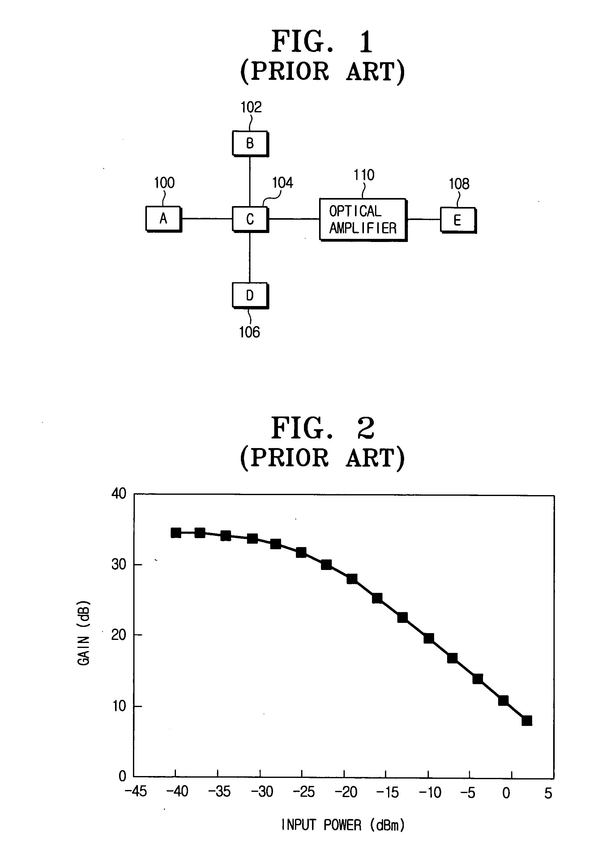
CROSS-REFERENCE TO RELATED APPLICATIONS [0001] This application claims priority from Korean Patent Application No. 2004-88352, filed on Nov. 2, 2004 in the Korean Intellectual Property Office, the entire disclosure of which is incorporated herein by reference. BACKGROUND OF THE INVENTION [0002] 1. Field of The Invention [0003] Apparatuses and methods consistent with the present invention relate to optical burst switching networks, and more particularly, to suppressing a surge occurring at an optical amplifier in an optical burst switching network. [0004] 2. Description of The Related Art [0005] In general, an optical signal may be classified into an optical circuit signal, an optical packet signal, or an optical burst signal. An optical circuit signal uses a preset optical path. In contrast, an optical packet signal and an optical burst signal do not use a preset optical path. [0006]FIG. 1 illustrates nodes that transmit and receive an optical signal over an optical communication ne...

Claims


Application Information

Patent Timeline
IPC IPC(8): H04B10/08
CPCH04B10/077H04B10/07955H04B10/564H04B10/25H04B10/2507H04B10/291
Inventor PARK, KEUN-JOOKIM, HYUN-CHINRHEE, JUNE-KOOSEO, YOUNG-KWANGYOUN, CHUN-JU
Owner SAMSUNG ELECTRONICS CO LTD
Why Eureka
Try Eureka