
Linear compressor

a compressor and linear technology, applied in the direction of machines/engines, positive displacement liquid engines, pumping pumps, etc., can solve the problem of difficult to reduce the size of the stator cover, and achieve the effect of reducing the number of elements of the linear compressor, reducing the size of the shell, and reducing the manufacturing cos

Inactive Publication Date: 2006-05-04
LG ELECTRONICS INC
View PDF4 Cites 28 Cited by
  • Summary
  • Abstract
  • Description
  • Claims
  • Application Information

AI Technical Summary

Benefits of technology

[0029] Therefore, the present invention has been made in view of the above problems, and it is an object of the present invention to provide a linear compressor having a stator cover, which is fabricated through sheet metal forming to have two or more curvatures, thereby enabling a size reduction of the shell and achieving a small-scale linear compressor.
[0030] It is another object of the present invention to provide a linear compressor which is designed in such a fashion that an oil cylinder is supported by a stator cover, thereby being capable of achieving a reduction in the number of elements, and a simplified structure of the linear compressor.
[0041] In the linear compressor according to the present invention, the stator cover is configured in such a fashion t h a t the section not formed with the bolt fastening through-holes has the curvature smaller than that of the section formed with the through-holes so as to enable a size reduction of the stator cover while defining a sufficient space between the stator cover and the shell, thereby enabling reduction of the size of the shell, achieving a small-scale linear compressor.
[0042] Further, according to the present invention, a curvature in a lower region of the stator cover is larger than that of an upper region of the stator cover in order to sufficiently support an end of the oil cylinder without requiring a separate supporting element, such as an oil suction cover. Thereby, the number of elements constituting the linear compressor is reduced, resulting in a reduction of the manufacturing cost. By omitting the oil suction cover, further, it is possible to prevent a deterioration of oil supply efficiency caused when the oil suction cover is misassembled, thereby being capable of improving operational reliability and reducing noise produced due to shaking of the oil suction cover.

Problems solved by technology

This has a problem in that it is difficult to reduce the size of the stator cover 27 and to achieve a small-scale linear compressor.

Method used


Image

  • Linear compressor
  • Linear compressor
  • Linear compressor

Examples


first embodiment

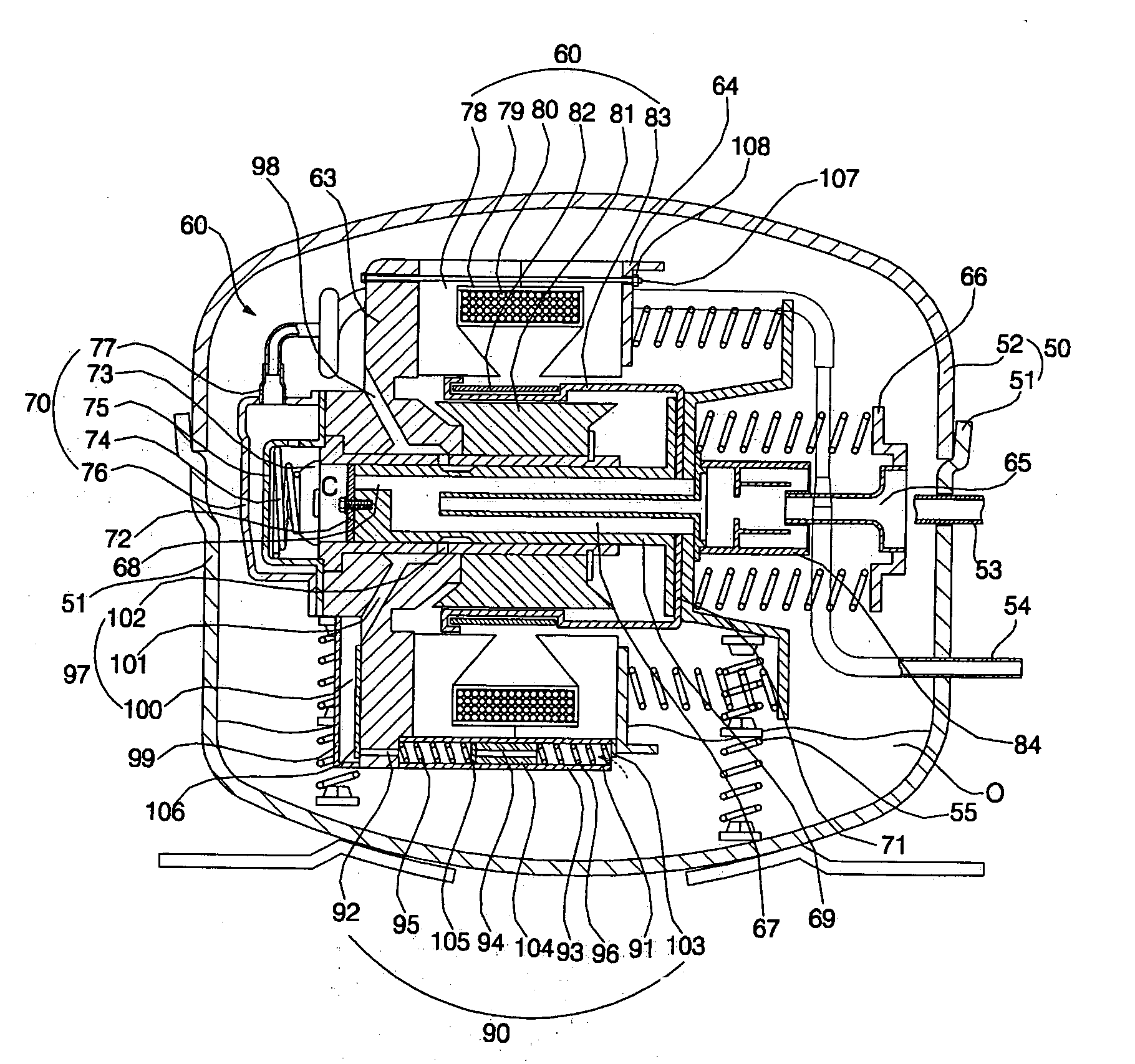
[0052]FIG. 3 is a front sectional view illustrating a linear compressor in accordance with the present invention.

[0053] As shown in FIG. 3, the linear compressor of the present invention comprises a linear compressing unit 60 mounted in a shell 50 in a shock-absorbing manner. The shell 50 is divided into a lower shell 51 having an open upper surface and an upper shell 52 configured to cover the upper surface of the lower shell 51. The lower and upper shells 51 and 52 are coupled to each other to define a hermetically sealed interior space therebetween. In a bottom region of the lower shell 51 is received oil O.

[0054] A fluid suction pipe 53 and a fluid discharge pipe 54 pass into the shell 50. The fluid discharge pipe 54 is also connected to the linear compressing unit 60 to discharge fluid, compressed in the linear compressing unit 60, to the outside. The linear compressing unit 60 is supported on dampers 55 mounted in the lower shell 51 so as to vibrate by means of the dampers 55...

second embodiment

[0088]FIG. 6 is a front sectional view illustrating a linear compressor in accordance with the present invention.

[0089] As shown in FIG. 6, the linear compressor according to the present embodiment comprises: a shell 120 for receiving oil O; a linear motor 121 mounted in the shell 120; a cylinder frame 122 mounted in front of the linear motor 121; a stator cover 123 mounted in rear of the linear motor 121; a piston 125 rectilinearly reciprocably disposed in a cylinder 124 mounted in the cylinder frame 122; fastening device for fixing the cylinder frame 122 and the stator cover 123 to each other; and oil supply device for supplying the oil O received in the shell 120 into a gap between the cylinder 124 and the piston 125.

[0090] The linear motor 121 comprises: outer stators 126 interposed between the cylinder frame 122 and the stator cover 123; a bobbin 127 provided inside the outer stators 126; a coil 128 wound on the bobbin 127; an inner stator 129 mounted on the cylinder frame 122...


PUM


Abstract

Disclosed herein is a linear compressor having a stator cover, which is designed in such a fashion that a section of the stator cover not to be fastened with bolts has a curvature smaller than the remaining section thereof to be fastened with the bolt so as to be reduced in size thereof. This enables the stator cover to be spaced apart from the shell by a sufficient distance, thereby achieving a size reduction of the shell and a small-scale linear compressor.

Description

BACKGROUND OF THE INVENTION [0001] 1. Field of the Invention [0002] The present invention relates to a linear compressor, and more particularly, to a linear compressor having a stator cover, which is fabricated through sheet metal forming to have two or more curvatures so as to be spaced apart from a shell by a sufficient distance, thereby enabling a size reduction of the shell and achieving a small-scale linear compressor. [0003] 2. Description of the Related Art [0004] Generally, linear compressors are machines used to suction and compress fluid, such as refrigerant gas, and discharge the compressed fluid as a piston is rectilinearly reciprocated in a cylinder by making use of driving power of a linear motor. [0005]FIGS. 1 and 2 are a front sectional view and a side sectional view, respectively, illustrating a linear compressor according to the prior art. [0006] As shown in FIGS. 1 and 2, the linear compressor of the prior art comprises: a shell 2 in which oil O is received; and a...

Claims


Application Information

Patent Timeline
Patent Type & Authority Applications(United States)
IPC IPC(8): F04B35/04F04B17/04
CPCF04B35/045F04B39/0276H02K1/145H02K1/185H02K7/14H02K33/06F04B39/023F16B5/02F16N7/38F16N13/02H02K33/16
Inventor OH, JIN TAEKLEE, JONG KOOSUH, KWANG HA
Owner LG ELECTRONICS INC
Features
  • Generate Ideas
  • Intellectual Property
  • Life Sciences
  • Materials
  • Tech Scout
  • Unparalleled Data Quality
  • Higher Quality Content
  • 60% Fewer Hallucinations
Learn More