
Channel simulator and wireless apparatus evaluation method

a wireless apparatus and simulator technology, applied in the field of channel simulators, can solve the problems of inability to perform agc and afc, inability to accurately perform performance evaluations, and inability to carry out agc and a

Inactive Publication Date: 2006-05-04
PANASONIC CORP
View PDF5 Cites 35 Cited by
  • Summary
  • Abstract
  • Description
  • Claims
  • Application Information

AI Technical Summary

Benefits of technology

[0021] It is an object of the present invention to provide a channel simulator and wireless apparatus evaluation method enabling transmission characteristics of a digital baseband processing section to be evaluated alone with excellence, irrespective of development of a radio circuit.

Problems solved by technology

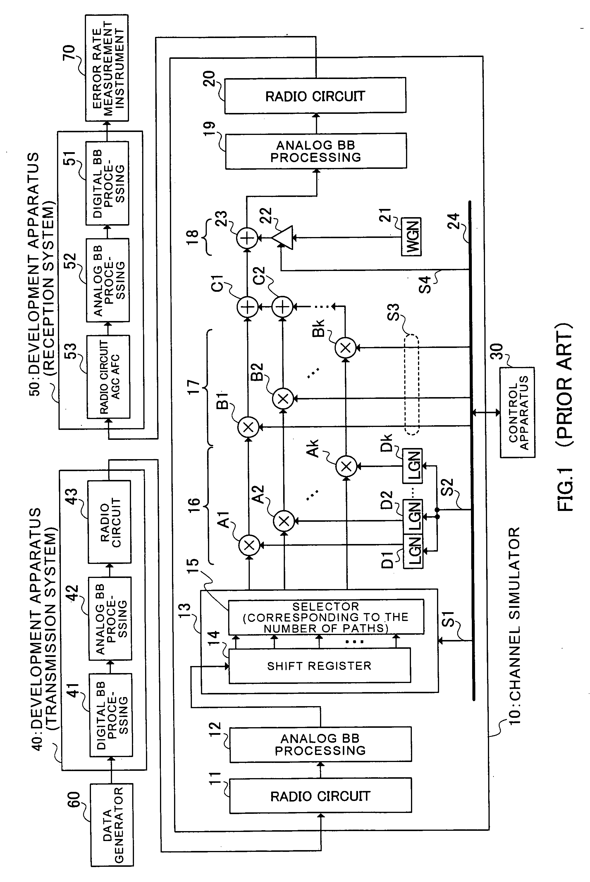
In particular, unless development of radio circuit 53 of reception system 50 proceeds to such an extent that the circuit is operable, it is not possible to perform AGC and AFC, and accurate performance evaluations cannot be carried out.
Therefore, it is not possible to check the operation of digital baseband processing sections 41 and 51 performing central processing until completion of radio circuits 43 and 53 (particularly, radio circuit 53 of the reception system 50), and there arises a problem that efficiency in development deteriorates corresponding to waiting for such completion.

Method used


Image

  • Channel simulator and wireless apparatus evaluation method
  • Channel simulator and wireless apparatus evaluation method
  • Channel simulator and wireless apparatus evaluation method

Examples


embodiment 1

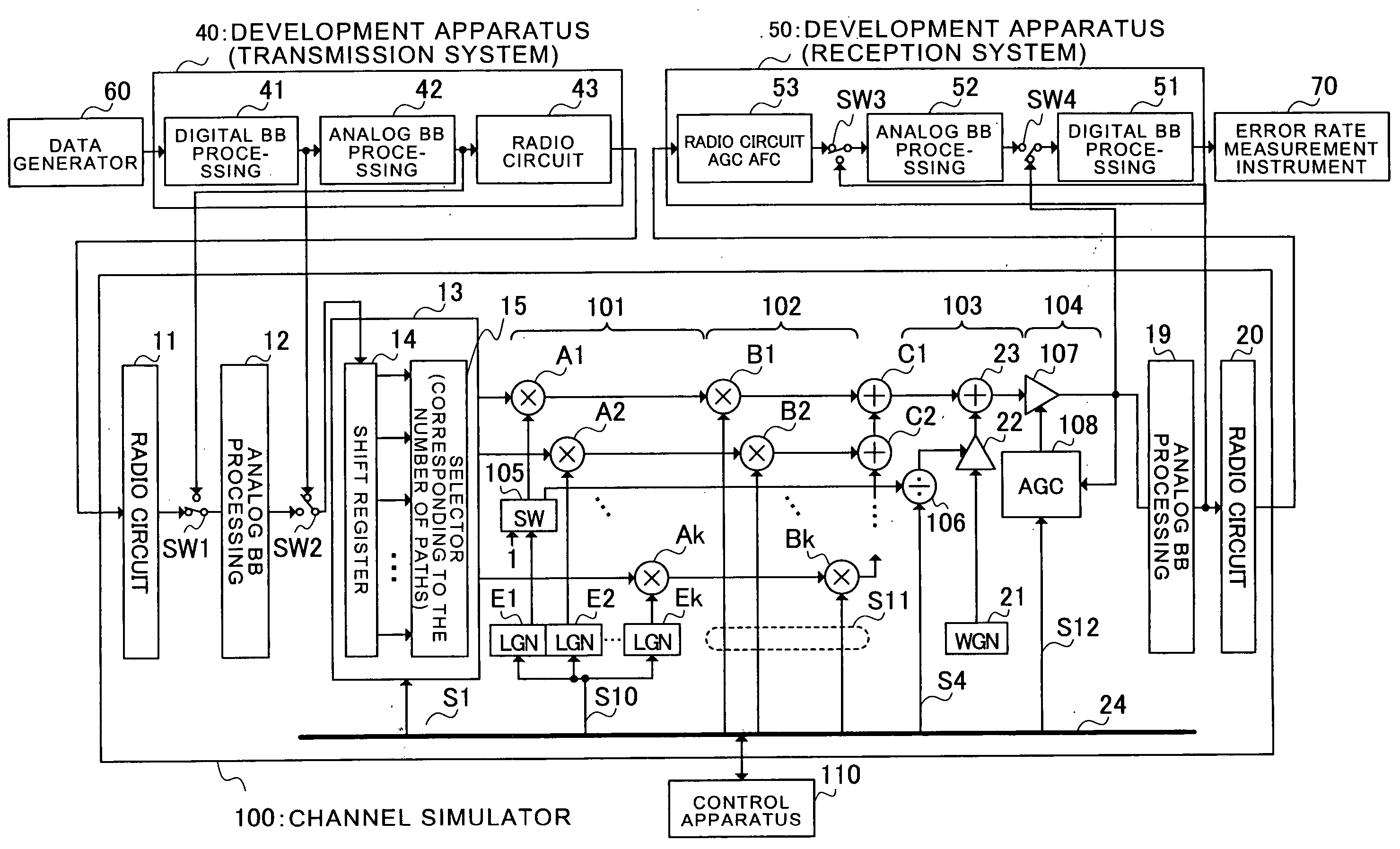
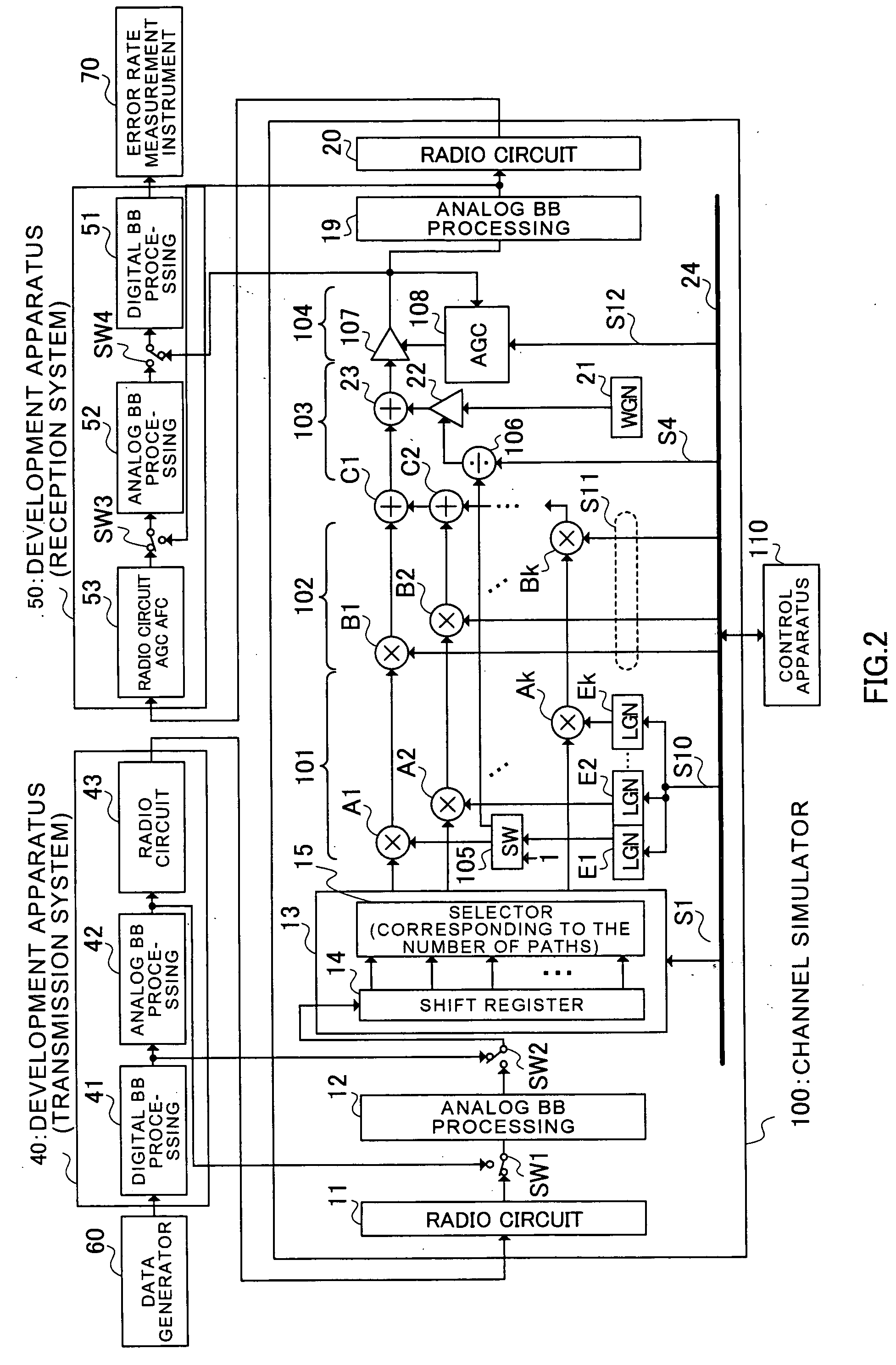
[0039]FIG. 2 illustrates a configuration of a channel simulator according to Embodiment 1 of the present invention, where the same sections as in FIG. 1 are assigned the same reference numerals as in FIG. 1. In addition, descriptions are omitted on the same sections as in FIG. 1. Further, as in FIG. 1, each line represents two baseband signal lines comprised of an I channel (in-phase i.e. the real part of a complex number) and a Q channel (quadrature i.e. the imaginary part of the complex number), except lines for output signals from radio circuits 43 and 20.

[0040] In channel simulator 100, switch SW1 is provided between radio circuit 11 and analog BB processing section 12, while switch SW2 is provided between analog BB processing section 12 and multipath signal generating section 13. By this means, in channel simulator 100, an output signal from digital BB processing section 41 of transmission system 40 can directly be input via switch SW2, while an output from analog BB processin...

embodiment 2

[0077]FIG. 5 illustrates a configuration of a channel simulator according to Embodiment 2 of the present invention, where the same sections as in FIG. 2 are assigned the same reference numerals as in FIG. 2. Channel simulator 200 of this Embodiment has the same configuration as that of channel simulator 100 of Embodiment 1 except transmission analog adjusting section 201 being provided before multipath signal generating section 13 and reception analog adjusting section 202 being provided after automatic gain control section 104.

[0078] By this means, in channel simulator 200, an output signal of digital BB processing section 41 is input via transmission analog adjusting section 201, the same channel simulation as in Embodiment 1 is performed on the signal processed in transmission analog adjusting section 201, and the signal subjected to the same channel simulation as in Embodiment is processed in reception analog adjusting section 202 and then, output to digital BB processing secti...


PUM


Abstract

An output signal of digital baseband processing section 41 is directly input, and receiver noise adding section 103 adds receiver noise simulating the SNR variation due to fading to the signal while keeping an entire signal level constant in single-path channel simulation, while in multipath channel simulation, instantaneous variation adding section 101 and short-term interval variation adding section 102 add only amplitude variations to respective signals of paths, and automatic gain control section 104 keeps a level of the path-combined signal constant, whereby it is possible to evaluate channel performance of digital baseband processing section 41 without waiting for development of radio circuit 53, i.e. without an AGC circuit and AFC circuit in reception system 50.

Description

TECHNICAL FIELD [0001] The present invention relates to a channel simulator for simulating a wireless channel to evaluate a wireless apparatus and a method of evaluating the wireless apparatus. BACKGROUND ART [0002] Conventionally, in developing a cellular telephone, a base station for the telephone, and MT and AP of wireless LAN, there is needed an apparatus for simulating a wireless channel as an environment for performance evaluation of a development apparatus, i.e. a channel simulator. [0003] By comparing transmission characteristics obtained by providing signals transmitted from a development apparatus with simulated fading and receiver noise using a channel simulator with theoretical values or computer simulation values, it is possible to judge whether the development apparatus performs desired operation. Further, by reproducing a channel state of a running experimental course, it is possible to analyze a failure of a development apparatus occurring under an actual propagation...

Claims


Application Information

Patent Timeline
Patent Type & Authority Applications(United States)
IPC IPC(8): H04B17/00H03C1/62
CPCH04B17/336H04B17/0087
Inventor INOGAI, KAZUNORIIMAMURA, DAICHIHOSHINO, MASAYUKIOTA, GENICHIRO
Owner PANASONIC CORP
Learn More