Prostate treatment stent

a stent and prostate technology, applied in the field of prostate treatment, can solve the problems of applicating force and expected to starve or otherwise kill the cells of the tissue trapped by the device, and achieve the effect of widening the urethra and avoiding traumatic effects on the tissu

Inactive Publication Date: 2006-05-04
PROTECH MEDICAL TECH
View PDF18 Cites 39 Cited by
  • Summary
  • Abstract
  • Description
  • Claims
  • Application Information

AI Technical Summary

Benefits of technology

[0012] An aspect of some embodiments of the invention relates to an implant device for removal of blocking tissue from the urethra. The device traps blocking tissue and applies force to the trapped tissue in order to cause the blocking tissue to fall out of ...

Problems solved by technology

The applied force is expected to starve or otherw...

Method used


Image

  • Prostate treatment stent
  • Prostate treatment stent
  • Prostate treatment stent

Examples


Embodiment Construction

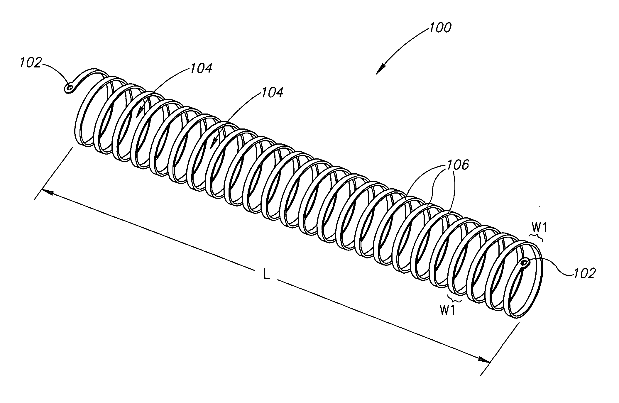
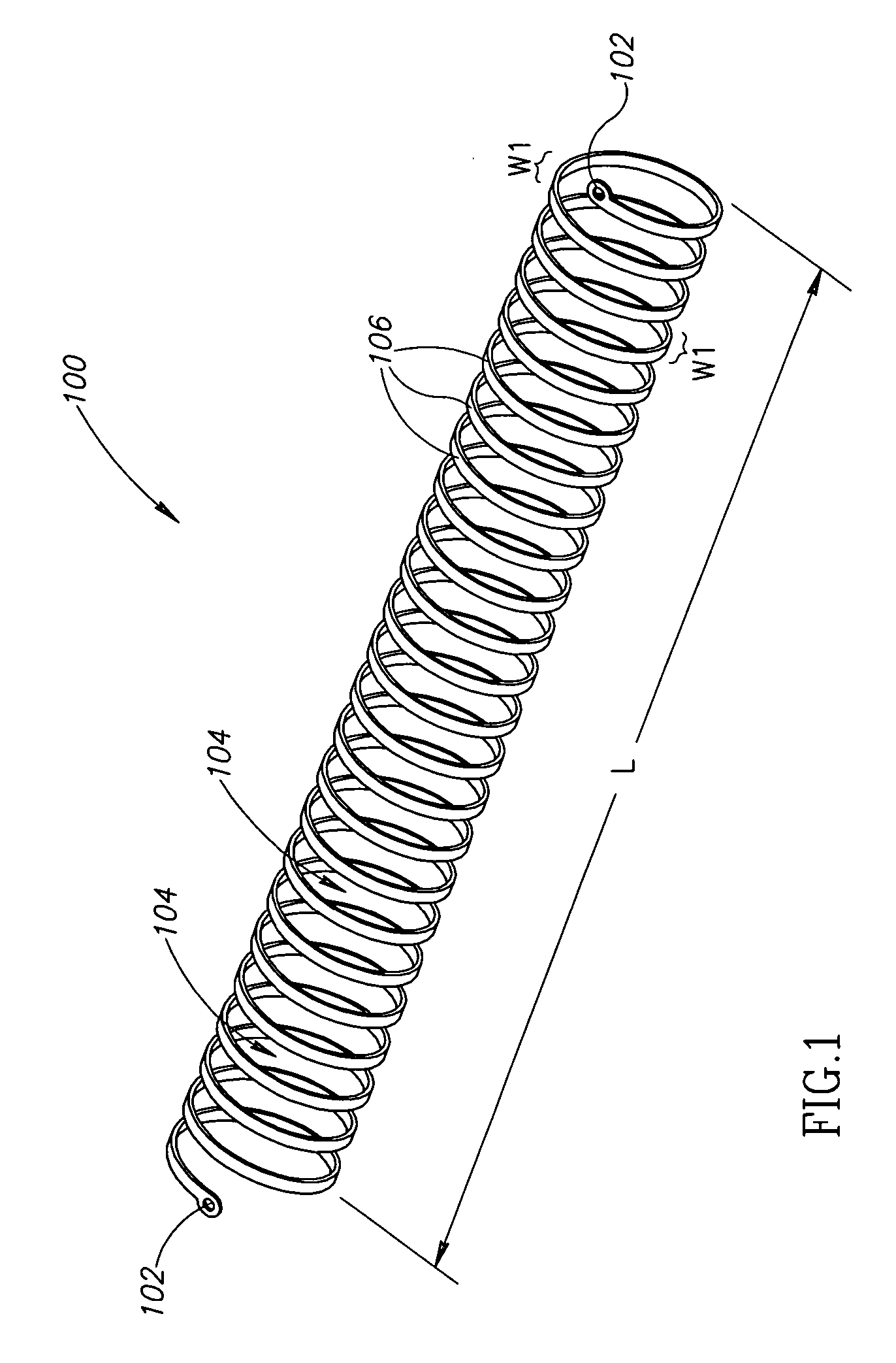
[0071]FIG. 1 is a schematic illustration of an elastic prostate implant 100, in accordance with an exemplary embodiment of the invention. Implant 100 includes an axially compressing device, such as a coil-shaped wire including a plurality of turns 106. Implant 100 has an elastic structure which axially compresses absent an external force. In FIG. 1, implant 100 is stretched such that gaps 104 are formed between turns 106. As described below, gaps 104 receive urethra-obstructing tissue which is to be removed and slowly press on the obstructing tissue until it is cut away and / or falls off due to tissue necrosis. In some embodiments of the invention, implant 100 includes anchoring structures, such as holes 102, at both ends, for use in stretching implant 100 to the state shown in FIG. 1. Holes 102 are optionally used during insertion of implant 100 to the urethra and / or for removal of the implant from the urethra.

[0072] Optionally, implant 100 is radially durable such that implant 100...


PUM


Abstract

A method of dissecting urethra obstructing tissue. The method includes capturing urethra obstructing tissue between portions of an implant and applying pressure on the tissue caught between the portions of the implant, for longer than 1 hour, until the tissue dies or falls off.

Description

PRIORITY APPLICATIONS [0001] The present application claims priority from Israel patent application 164563, filed on Oct. 13, 2004, the disclosure of which is incorporated herein by reference. FIELD OF THE INVENTION [0002] The present invention relates to the field of prostate treatment. BACKGROUND OF THE INVENTION [0003] Benign prostate enlargement is a common affliction among older men. Prostate enlargement involves swelling of the prostate, which blocks the urinary path. A common treatment for prostate enlargement is resection, which includes cutting away a portion of the prostate gland. The resection may be performed by a scalpel inserted through the penis to the prostate using a resectoscope. In such a procedure, however, the view of a physician performing the resection is limited and a mistaken move of the physician may cause serious damage to the patient. Other methods of treatment of benign prostate enlargement include heat treatment and / or low temperature ablation. [0004] U...

Claims


Application Information

Patent Timeline
IPC IPC(8): A61B17/32A61B18/18A61B17/00A61B17/08A61FA61F2/88
CPCA61B17/08A61B2017/00274A61B2018/00547A61F2/88A61B2017/32096
Inventor SIVAN, TOVYKILEMNIK, IDO
Owner PROTECH MEDICAL TECH
Why Eureka
Try Eureka