Stent and method of manufacturing same

a technology of stents and manufacturing methods, applied in the field of stents, can solve the problems of tearing the stent, wires moving with respect, and the stent creates weaknesses in the sheath, and achieves the effects of easy manufacturing and operation, large resistance to radial compression, and easy positioning

Inactive Publication Date: 2006-05-04
BAYLIS MEDICAL
View PDF24 Cites 197 Cited by
  • Summary
  • Abstract
  • Description
  • Claims
  • Application Information

AI Technical Summary

Benefits of technology

[0018] Advantageously, the stent is relatively easy to manufacture and to operate. The stent is also expandable in relatively small vessels without restricting excessively the flow of body fluids within the vessel.
[0019] The stent is also relatively easy to position so that it is expanded at a desired location. Furthermore, the relatively large resistance to radial compression of the scaffold second section helps in keeping the body lumen open after the stent has been implanted.

Problems solved by technology

For example, stitches create weaknesses in the sheath.
Accordingly, stress concentrations around these weaknesses may tear the sheath.
In addition, the stitches provide locations from which undesirable calcifications may grow.
Accordingly, if a similar stent were made so that it could be expanded from a retracted configuration to an expanded configuration, the wires would move with respect to each other and would likely stretch and tear the polymer forming the sheath.
Similarly to the stitches used to attach sheaths to scaffolds, these stitches create stress concentrations that may produce tears in the valve while it is in use or when it is deployed.
Furthermore, such valves are relatively time-consuming to manufacture and require that specialized personnel be used to stitch the valve to the scaffold.
Yet, furthermore, the stitches typically protrude from the stent and therefore increase the compressed size or delivery size of the stent.
Thus, such stents may be unsuitable for use in relatively small body vessels.
It would therefore be relatively hard to control the deployment of such a valve during deployment if it were included in a collapsible stent.
Another problem encountered in expandable stents is that during deployment, a radial expansion causes a longitudinal retraction of the stent.
These retractions make the stent relatively difficult to position accurately so that it ends up at the suitable location after deployment is complete.
However, these sections have a geometry rendering these stents relatively weak in radial compression.

Method used


Image

  • Stent and method of manufacturing same
  • Stent and method of manufacturing same
  • Stent and method of manufacturing same

Examples


Embodiment Construction

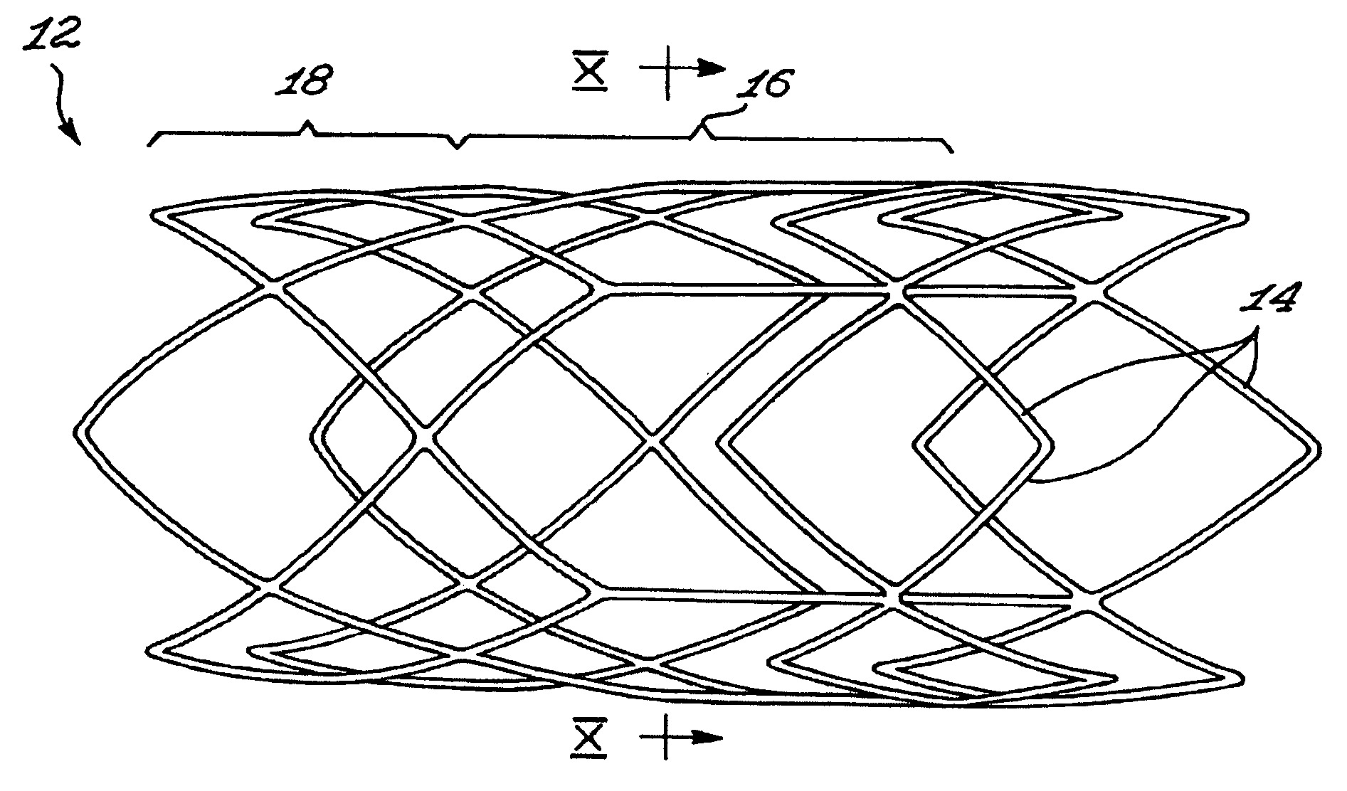
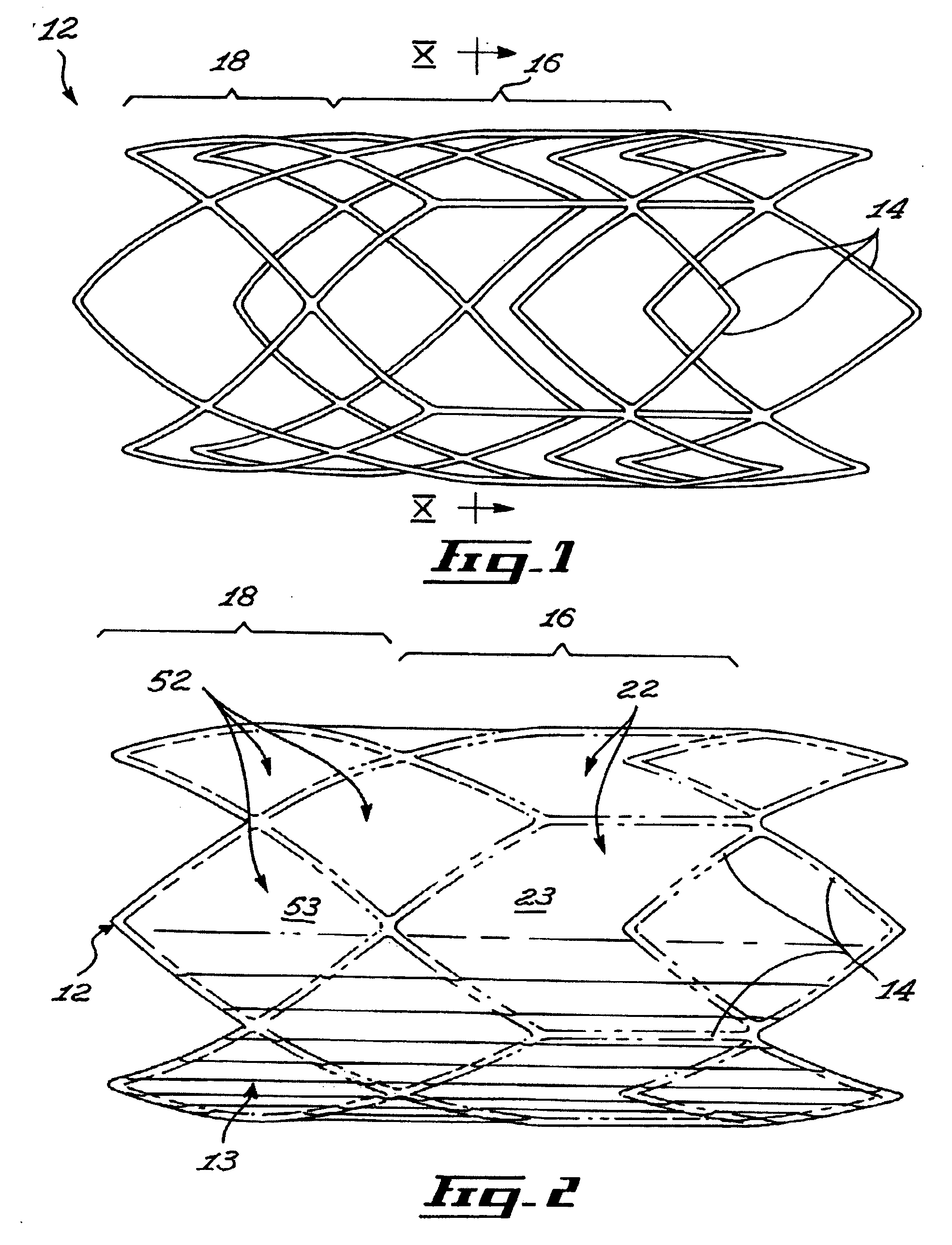
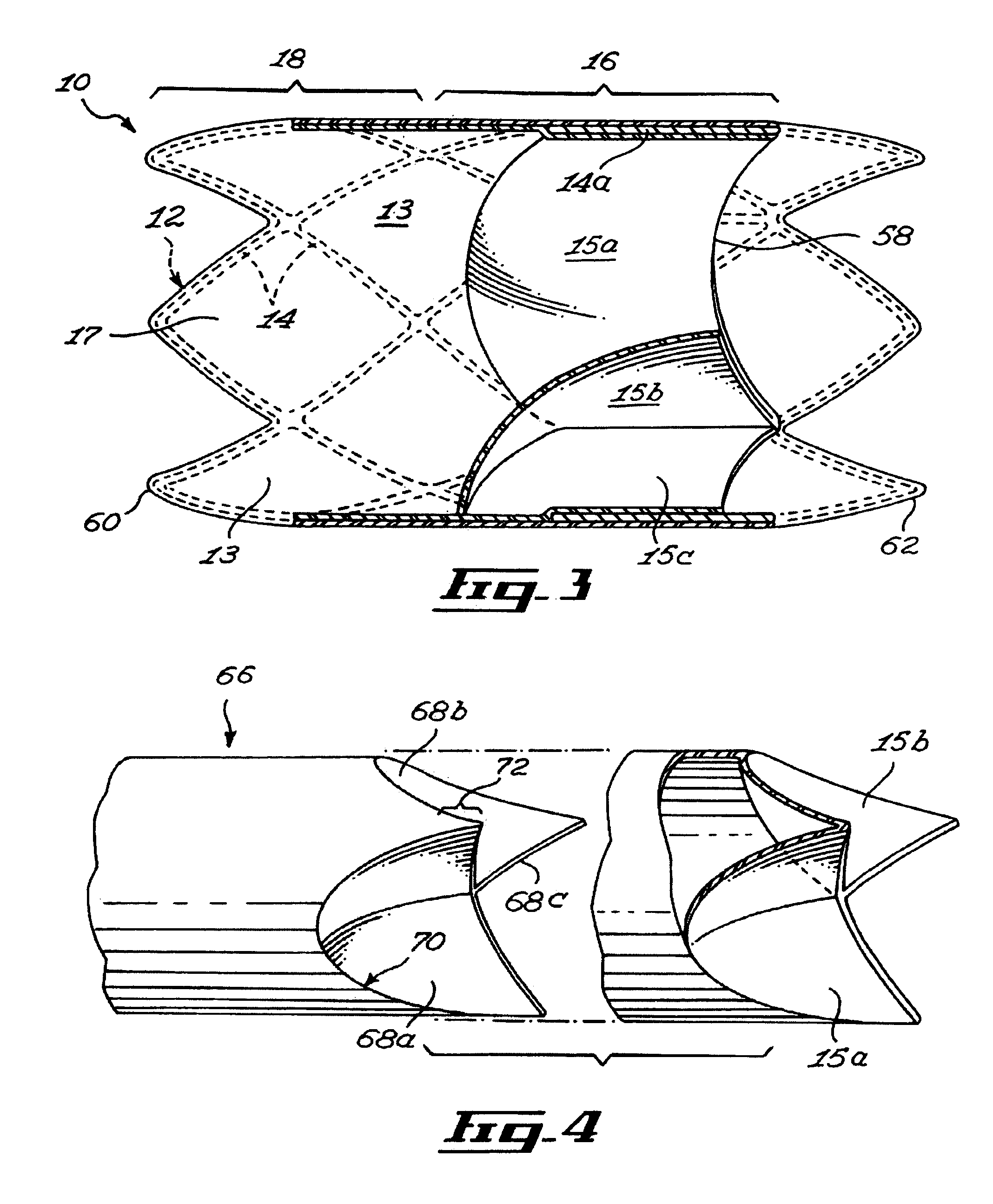
[0042]FIG. 3 shows a stent 10 insertable in a body lumen (not shown in the drawings), the stent 10 defining a stent longitudinal axis. The stent includes a scaffold 12, a sheath 13 and valve leaflets 15, 15a and 15b. The sheath 13 and the valve leaflets 15a, 15b and 15c are mounted to the scaffold 12.

[0043] The scaffold 12 includes a scaffold passageway 17 that extends substantially longitudinally through the scaffold 12. The valve leaflets 15a, 15b and 15c extend at least partially across a scaffold passageway 17.

[0044] Referring to FIG. 1, the scaffold 12 includes interlinked struts 14 forming the scaffold first section 16 and a scaffold second section 18. The struts 14 are any suitable substantially elongated members interconnected in any suitable manner. For example, the struts 14 each include a substantially elongated metallic member of substantially uniform cross-section, the struts 14 extending integrally from each other. In other embodiments of the invention, struts are se...


PUM


Abstract

A stent insertable in a body lumen. The stent includes a scaffold having interlinked struts forming a scaffold first section and a scaffold second section, the scaffold being deformable substantially radially between a scaffold retracted configuration and a scaffold expanded configuration. The struts are configured and sized such that the coefficient of radial compressibility of the scaffold second section is greater than the coefficient of radial compressibility of the scaffold first section and the coupling coefficient between radial and longitudinal strains of the scaffold second section is greater than the coupling coefficient between radial and longitudinal strains of the scaffold first section.

Description

[0001] The present invention claims priority from Provisional Application Ser. No. 60 / 619,298 filed on Oct. 15, 2005. This application is also a Continuation-in-Part of U.S. patent application Ser. No. 10 / 841,816 filed on May 10, 2004. [0002] I hereby claim the benefit under Title 35, United States Code, § 120, of the prior, co-pending United States application listed herinabove and, insofar as the subject matter of each of the claims of this application is not disclosed in the manner provided by the first paragraph of Title 35, United States Codes § 112, I acknowledge the duty to disclose material information as defined in Title 37, Code of Federal Regulations, § 1.56(a), which occurred between the filing date of this application and the national or PCT international filing date of this application Ser. No. 10 / 841,816, Filed on May 10, 2004.FIELD OF THE INVENTION [0003] The present invention relates generally to prosthetic devices. More specifically, the present invention is concer...

Claims


Application Information

Patent Timeline
Patent Type & Authority Applications(United States)
IPC IPC(8): A61F2/06A61F2/82
CPCA61F2/2418A61F2230/0054A61F2250/0018A61F2002/825
Inventor BLADILLAH, YOUSSEFBAYLIS, FRANK
Owner BAYLIS MEDICAL
Why Eureka
Try Eureka