Method for controlling temperature in a diesel particulate filter during regeneration

Active Publication Date: 2006-05-11
SOUTHWEST RES INST
View PDF7 Cites 74 Cited by
  • Summary
  • Abstract
  • Description
  • Claims
  • Application Information

AI Technical Summary

Problems solved by technology

Increasingly restrictive emissions regulations, particularly for Diesel engines, permit very little particulate matter (PM) to be emitted from an engine.
PM accumulation in the DPF causes an increase in the pressure drop across the DPF (DPF-ΔP), which has an adverse effect on engine fuel economy.
Therefore, the DPF must be regenerated before the PM loading reaches an undesirable level.
However, the thinner materia

Method used


Image

  • Method for controlling temperature in a diesel particulate filter during regeneration
  • Method for controlling temperature in a diesel particulate filter during regeneration
  • Method for controlling temperature in a diesel particulate filter during regeneration

Examples


Embodiment Construction

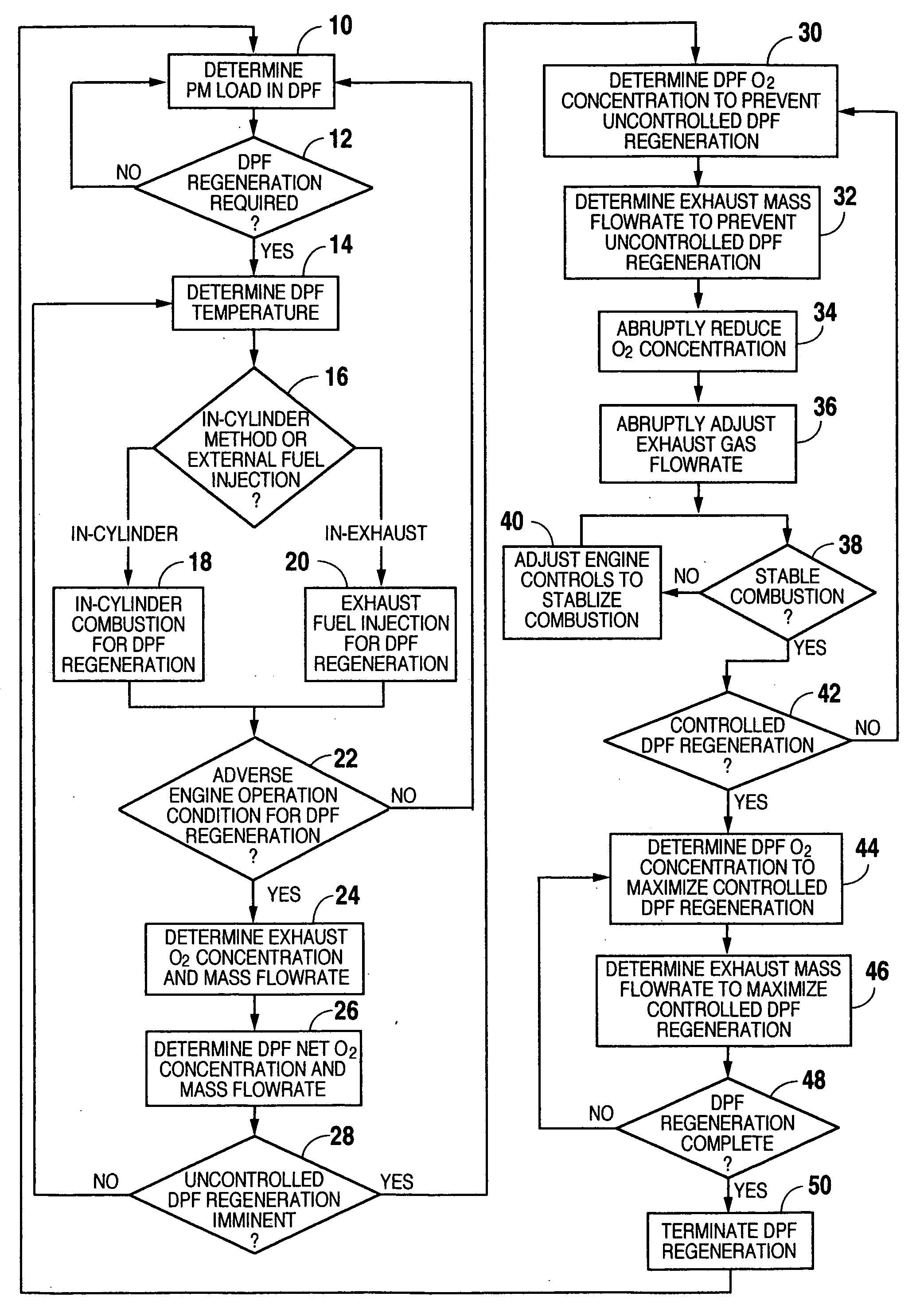
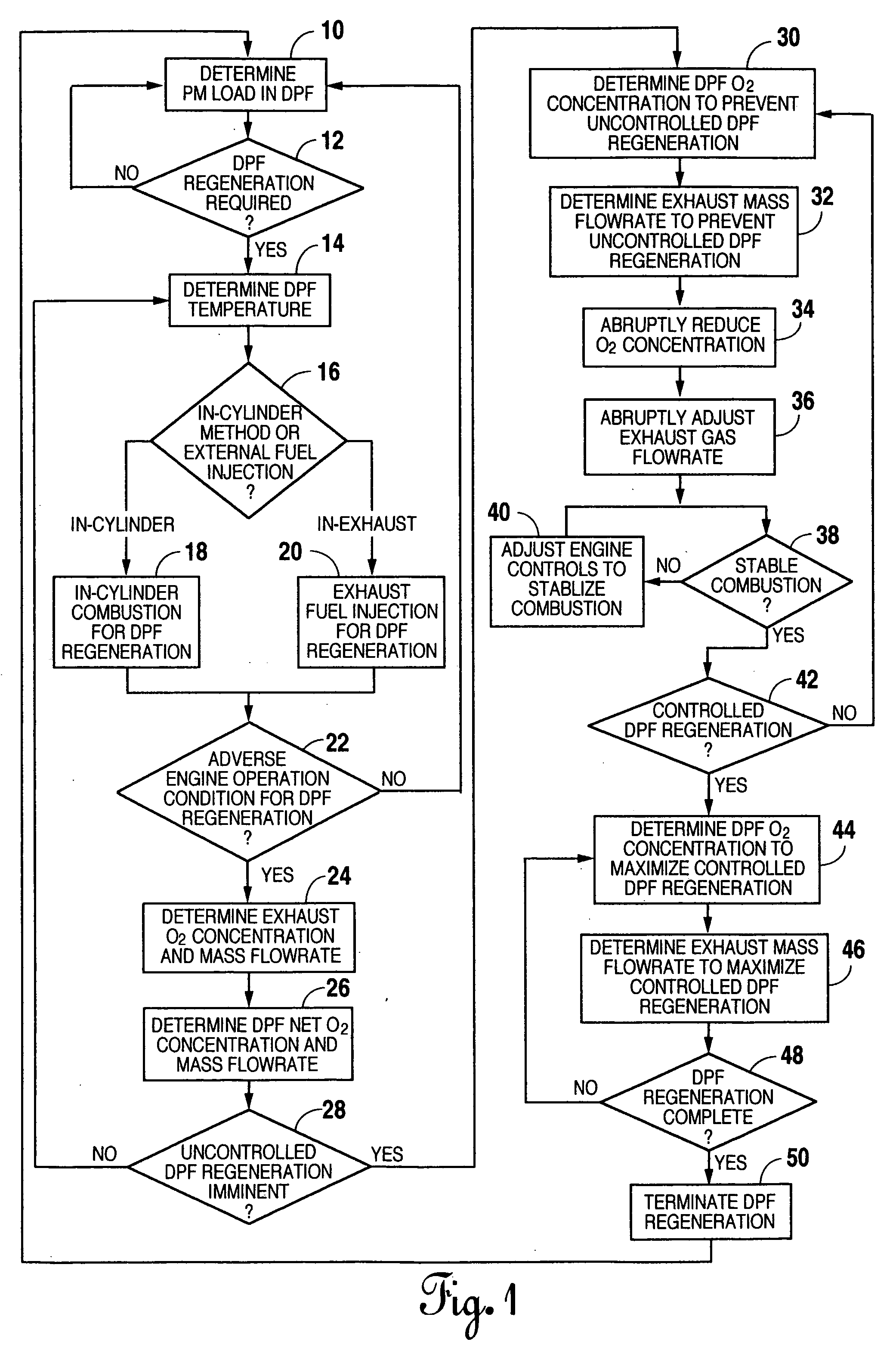
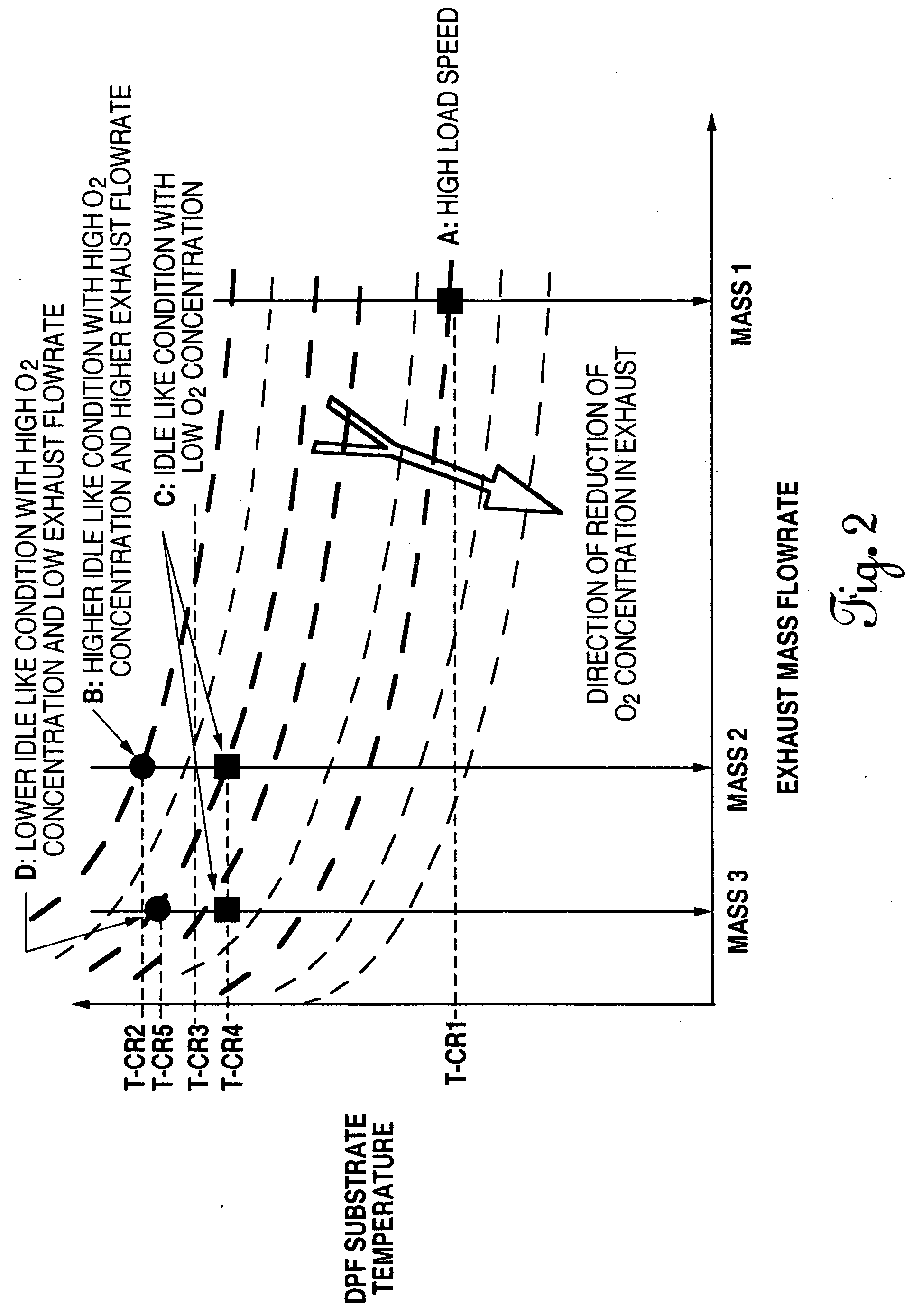
[0015] There are three major parameters that affect the chemical reaction rates during DPF regeneration: the amount of PM loaded in the DPF, temperature, and O2 and NO2 concentrations in the exhaust stream. During regeneration, the particulate matter build-up inside a DPF is oxidized by a reaction with oxygen. In accordance with the present invention, after DPF regeneration is initiated, the regeneration rate is controlled by controlling O2 concentration and exhaust flowrate. High O2 concentrations in the exhaust stream may cause uncontrolled regeneration under low exhaust flowrate conditions.

[0016] Under normal operating conditions, DPF traps particulate matter from the exhaust. As particulate matter accumulates in the DPF, the exhaust pressure at the DPF inlet increases causing a loss in combustion efficiency. Therefore, before the loss of efficiency becomes significant, the DPF should be regenerated or cleaned.

[0017] Diesel particulate filter regeneration can be initiated durin...


PUM


Abstract

Uncontrolled regeneration in a Diesel particulate filter is prevented by controlling the concentration and mass flowrate of oxygen passing through the Diesel particulate filter during regeneration.

Description

BACKGROUND OF THE INVENTION [0001] This is a non-provisional application claiming priority to U.S. Provisional Application Ser. No. 60 / 625,324 filed Nov. 5, 2004.TECHNICAL FIELD [0002] This invention relates generally to a method for regenerating Diesel particulate filters and more particularly to such a method whereby uncontrolled regeneration of the Diesel particulate filter is prevented. BACKGROUND ART [0003] Increasingly restrictive emissions regulations, particularly for Diesel engines, permit very little particulate matter (PM) to be emitted from an engine. Particulate matter is the term used for the solids emitted by an engine. PM comprises mostly carbon soot and hydrocarbons. Soot is more than just black smoke; it is also made up of a large number of ultra-fine particles that are invisible to the naked eye. [0004] Diesel particulate filters, or DPFs, are used to control emissions of PM from Diesel engine exhaust. Diesel particulate filters are also known as soot filters or D...

Claims


Application Information

Patent Timeline
IPC IPC(8): F01N3/00
CPCF01N9/002F01N9/005F01N2560/06F02D41/0055F02D41/029F02D2200/0802F02D2200/0812Y02T10/47Y02T10/40
Inventor ZHAN, RIJINGHUANG, YIQUNKHAIR, MAGDI K.
Owner SOUTHWEST RES INST
Why Eureka
Try Eureka