System with camshaft and camshaft receptacle

a technology of camshaft and receptacle, which is applied in the direction of machine/engine, valve drive, auxillary lubrication, etc., can solve the problems of low load-bearing force, reduced assembly steps, and low load-bearing force, so as to avoid mixed friction or high solid friction in the bearing face, easy to be actuated, and high bearing load

Inactive Publication Date: 2006-05-11
FORD GLOBAL TECH LLC
View PDF3 Cites 2 Cited by
  • Summary
  • Abstract
  • Description
  • Claims
  • Application Information

AI Technical Summary

Benefits of technology

[0021] The rotating camshaft is in this case carried by a wide hydrodynamic lubricating oil film which is formed in the bearing point and bearing shells. The camshaft mounting according to the invention can in this case absorb higher bearing loads in the region of the bearing saddles as a result of a wider plain bearing face, without leaving the fluid friction zone. Mixed friction or high solid friction in the bearing face can be avoided.
[0022] As a result, using a system according to the present invention, a fuel pump arranged above the camshaft can easily be actuated via an additional control cam arranged on the camshaft, without there having to be the fear that the camshaft runs dry in the region of the bearing saddle.
[0023] The embodiments of the system are advantageous in which in each case the two bearing half shells provided at a bearing point are fixed with respect to the camshaft. This makes it possible to install the camshaft, with bearing half shells already arranged on the latter in the installation position, as a preassembled structural unit. This not only reduces the number of assembly steps during assembly, but also reduces the number of individual parts to be kept in stock and to be administered and, consequently, the overall production costs.
[0024] The bearing shells are in this case fixed at least in such a way that they do not come loose from the camshaft and are not lost. Fixing may, however, be executed even more comprehensively. Thus, the bearing half shells may be fixed axially in such a way that they cannot be displaced in the direction of the longitudinal axis of the camshaft. This affords advantages, since, during assembly, the bearing shells are then positioned directly in the bearing saddles and bearing covers provided for them, without a readjustment, that is to say an axial alignment, of the shells becoming necessary. The bearing shells may also be fixed securely against twisting, so that the joint, as it is known, that is to say the region in which the two parting planes of the half shells lie opposite one another, comes to lie in a predetermined position in the circumferential direction.

Problems solved by technology

One disadvantage of the small width of the bearing saddles which serve for mounting the camshaft is, in particular, the low load-bearing force.
If, however, the camshaft is additionally used in order to actuate a fuel pump, this results in loads from the camshaft which press the camshaft into the narrow bearing saddles.
This not only reduces the number of assembly steps during assembly, but also reduces the number of individual parts to be kept in stock and to be administered and, consequently, the overall production costs.

Method used


Image

  • System with camshaft and camshaft receptacle
  • System with camshaft and camshaft receptacle
  • System with camshaft and camshaft receptacle

Examples


Embodiment Construction

)

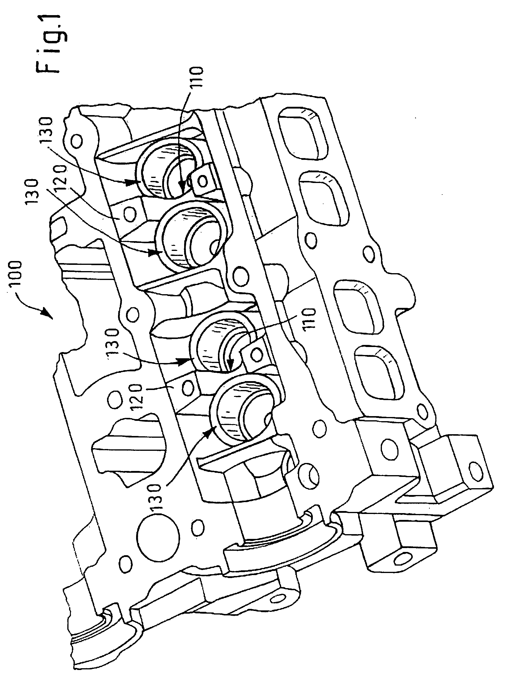
[0044]FIG. 1 shows a lower part of a camshaft receptacle 100 according to the prior art. The camshaft receptacle 100 illustrated has two bearing saddles 110 which are incorporated into two webs 120 provided in the lower part of the camshaft receptacle 100. On the right and left of the webs 120 are provided four circular pockets or chambers 130 which serve, during assembly, for providing a passage for the insertion of the tappets. The confined space conditions or the need for arranging the chambers 130 lead ultimately to the formation of very narrow bearing saddles.

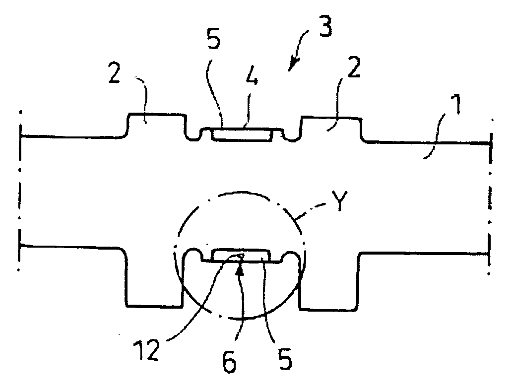
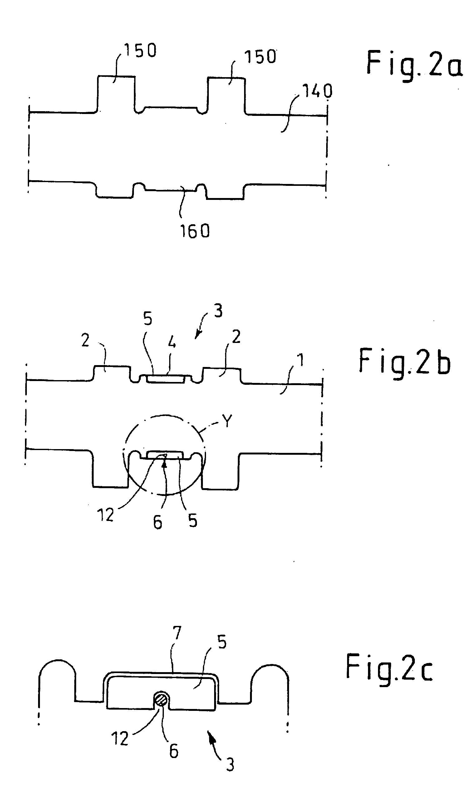
[0045]FIG. 2a shows diagrammatically a portion of a camshaft 140 according to the prior art in a side view and partially in section.

[0046] The illustrated portion of the camshaft 140 has two cams 150, between which a thickened shaft shoulder 160 is provided. This shaft shoulder 160 serves for mounting the camshaft 140 in the camshaft receptacle and for this purpose is received (not illustrated), in the lower part of the...


PUM

PropertyMeasurementUnit
widthaaaaaaaaaa
adhesive bondaaaaaaaaaa
surface areaaaaaaaaaaa

Abstract

The invention relates to a system, comprising a camshaft with at least two bearing points, a two-part camshaft receptacle which has, in a lower part, at least two bearing saddles and, in an upper part, at least two bearing covers corresponding to the bearing saddles, the camshaft being mounted with its bearing points in the bearing saddles and bearing covers. Further, bearing half shells are provided, of which in each case two are arranged in pairs between a bearing point and the bearing saddle and bearing cover receiving this bearing point, so that, the bearing half shells are supported on the bearing saddle or bearing cover and in each case two bearing half shells, together with a bearing point form a radial plain bearing.

Description

FIELD OF INVENTION [0001] The invention relates to an improved camshaft mounting system, and more particularly to a system with a camshaft having at least two bearing points and with a two-part camshaft receptacle which has, in a lower part, at least two bearing saddles and, in an upper part, at least two bearing covers corresponding to the bearing saddles, the camshaft being mounted with its bearing points in the bearing saddles and bearing covers. BACKGROUND AND SUMMARY OF THE INVENTION [0002] The operating method of a four-stroke internal combustion engine comprises the charge exchange in addition to the compression of the fuel / air mixture or of the combustion air and to the expansion as a result of the combustion taking place in the combustion space. Within the framework of the charge exchange, the expulsion of the combustion gases via the outlet valves and the filling of the combustion space with fresh mixture or fresh air by the inlet valves take place. To control the charge e...

Claims


Application Information

Patent Timeline
Patent Type & Authority Applications(United States)
IPC IPC(8): F01L1/04
CPCF01L1/053F01L1/46Y10T29/49293F01L2820/01Y10T29/49645F01L2001/0476
Inventor BARTSCH, GUENTER
Owner FORD GLOBAL TECH LLC
Why Eureka
Try Eureka