Heater, wafer heating apparatus and method for manufacturing heater

a technology of heating apparatus and wafer, which is applied in the direction of ohmic-resistance heating, electrical equipment, hot plate heating arrangements, etc., can solve the problems of complex process, complex and delicate control, and inability to meet the requirements of volume production, and achieve the effect of shortening the time period

Active Publication Date: 2006-05-11
KYOCERA CORP
View PDF8 Cites 82 Cited by
  • Summary
  • Abstract
  • Description
  • Claims
  • Application Information

AI Technical Summary

Benefits of technology

[0051] Accordingly, an object of the present invention is to provide a heater that is capable of heating a wafer or other object to a desired temperature i

Problems solved by technology

There has been a demand for a heater that can heat a wafer with more uniform temperature distribution with a simpler structure, since it is difficult to achieve uniform temperature distribution with the conventional heater and it is necessary to carry out very complex and delicate control procedure to achieve a uniform temperature distribution.
Thus it is desired to stabilize the wafer temperature in uniform temperature distribution with about 60 seconds after placing the wafer on a heater, but the conventional heater cannot satisfy this requirement because it takes a long period of time to stabilize the temperature.
There has also been such a problem that a heater comprising a coil-shaped resistive heating member embedded therein has a tendency of the density of the heating member changing significantly between the outside and inside at a bending portion of the resistive heating

Method used


Image

  • Heater, wafer heating apparatus and method for manufacturing heater
  • Heater, wafer heating apparatus and method for manufacturing heater
  • Heater, wafer heating apparatus and method for manufacturing heater

Examples


embodiment 1

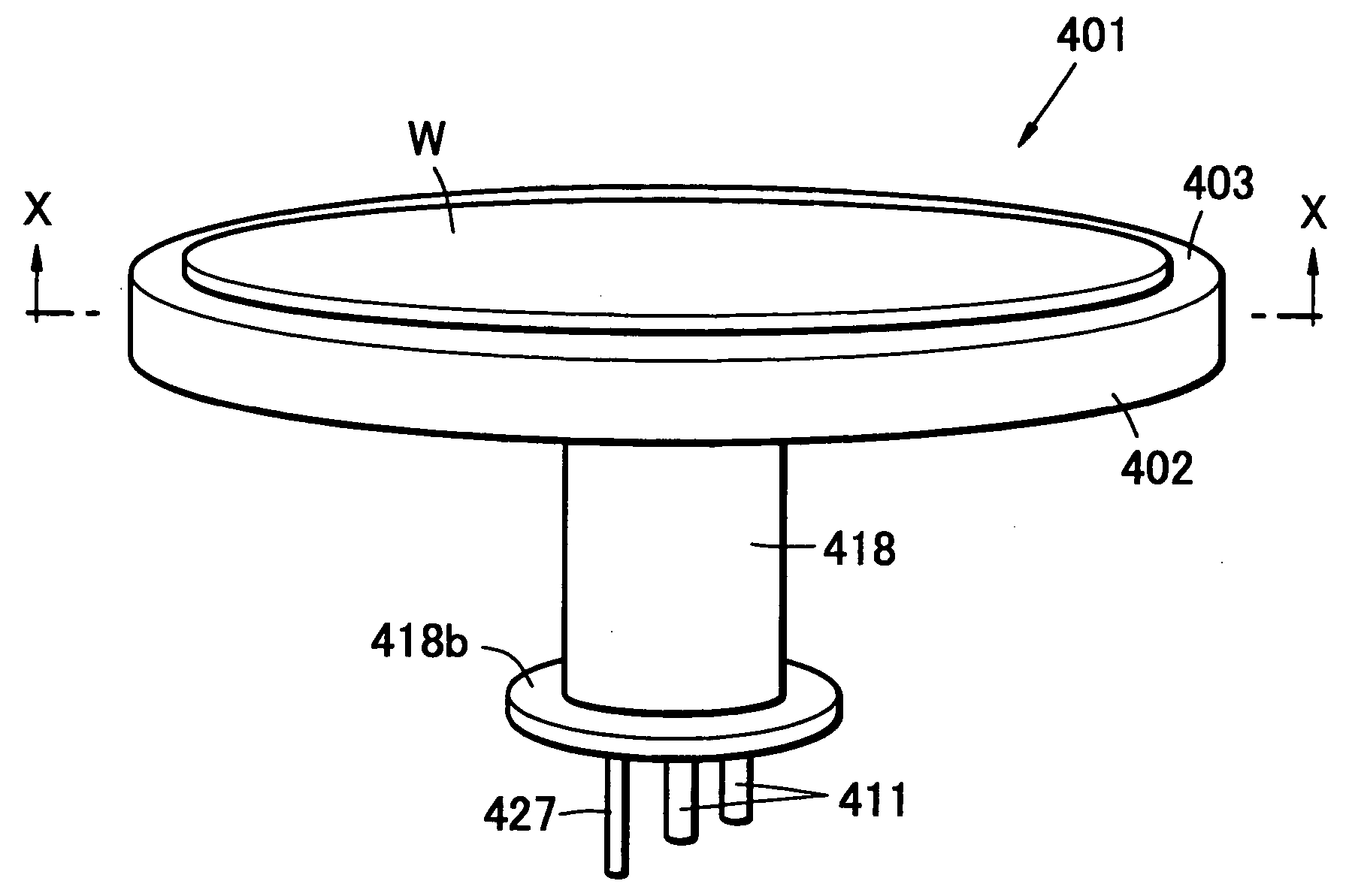
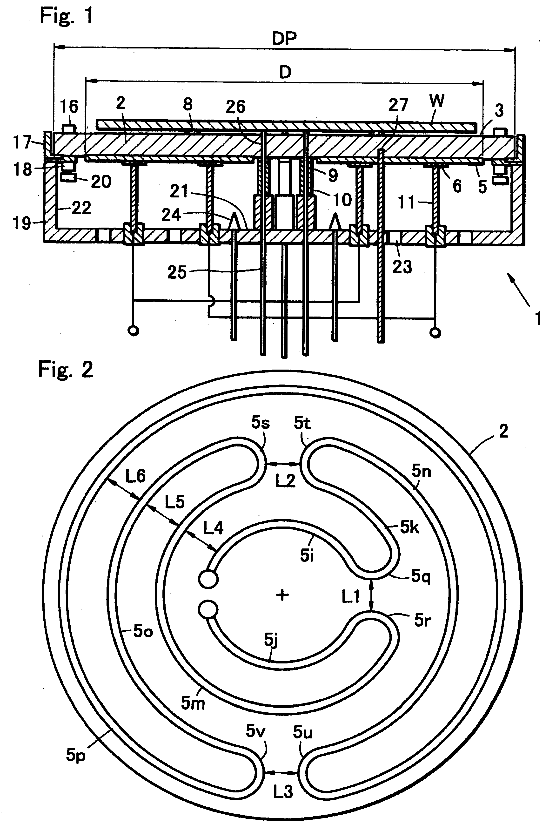
[0123]FIG. 1 is a sectional view showing the constitution of a heater 1 according to a first embodiment of the present invention. The heater 1 of the first embodiment comprises a plate-shaped ceramic member 2, power feeder sections 6, power terminals 11 and a metal casing 19.

[0124] According to the first embodiment, the plate-shaped ceramic member 2 is made of a ceramic material consisting of silicon carbide or aluminum nitride as the main component, for example, and has one principal surface used as a mount surface 3 to place the wafer W thereon and a resistive heating member 5 is formed as described below on the other principal surface.

[0125] The power feeder sections 6 are electrically connected to the resistive heating member 5 that is formed on the other principal surface of the plate-shaped ceramic member 2, while the power terminals 11 are connected to the power feeder sections 6.

[0126] The metal casing 19 holds the power terminals 11 connected to the power feeder sections...

embodiment 2

[0239] A heater according to the second embodiment of the present invention is constituted similarly to the heater 1 of the first embodiment, except for the positioning of the temperature measuring element 27 that is specified in relation to the resistive heating member 5 and the power feeder section 6. In the second embodiment, preferable form is similar to that of the first embodiment. In the drawings referred to in the second embodiment, components similar to those of the first embodiment will be identified with similar reference numerals.

[0240] The heater according to the second embodiment of the present invention has such a constitution as one of the principal surfaces of the plate-shaped ceramic member 2 is used as a mount surface (heating surface) 3 for heating an object, with the resistive heating member 5 running in a U shaped configuration comprising a plurality of arc bands and linkage arc band inside or on the other principal surface, and the temperature measuring eleme...

embodiment 3

[0245]FIG. 7A is a sectional view showing the constitution of a heater 300 according to the third embodiment of the present invention.

[0246] The heater 300 of the third embodiment has such a constitution as an example of which is shown in FIGS. 7A, 7B where three or more peripheral protrusions 304 are provided along the periphery of the mount surface 3 and inner protrusions (wafer support pin) 8 that are lower than the peripheral protrusions 304 in height are provided inside of the peripheral protrusions 304, so that the peripheral protrusions 4 are held so as to be movable in at least one of radial direction of the plate-shaped ceramic member and vertical direction. Constitution of the third embodiment is similar to that of the first embodiment except for the points described below.

[0247] In the third embodiment, as shown in FIGS. 8A, 8B, a space is secured between fastening holes 12 of the peripheral protrusions 304 and the bolts 10 that fasten the peripheral protrusions 304, so...


PUM


Abstract

A heater that is capable of heating a object to a desired temperature in a short period while minimizing the temperature difference the surface of the object is provided. The heater comprising a plate having a first surface and a second surface, the first surface being a mount surface whereon an object is placed and having a resistive heating member; wherein the resistive heating member is formed in a continuous band having arc bands located on one of two concentric circles of different radii, at least one arc band located on the other circle, and linkage arc band that connects the arc band located on the one circle and the arc band located on the other circle; while the distance between the adjacent linkage arc bands is smaller than the distance between the arc band located on the one circle and the arc band located on the other circle.

Description

BACKGROUND OF THE INVENTION [0001] 1. Field of the Invention [0002] The present invention relates mainly to a heater used in heating a wafer, a wafer heating apparatus and a method for manufacturing the heater. [0003] 2. Description of the Related Art [0004] In a manufacturing process of semiconductor devices, a heater is used to heat a semiconductor wafer (hereinafter referred to simply as a wafer) during formation of thin semiconductor film, etching, baking of resist film and other steps. [0005] For such heating purposes, for example, Patent Document 1, Patent Document 2 and Patent Document 3 disclose wafer heating apparatus as shown in FIG. 16. [0006] A heater 771 comprises a plate-shaped ceramic member 772 and a metal casing 779 as major components, and is constituted by securing the plate-shaped ceramic member 772 made of a ceramic material of nitride or carbide on an opening of the bottomed metal casing 779, that is made of a metal such as aluminum, via an insulating contact m...

Claims


Application Information

Patent Timeline
IPC IPC(8): H05B3/68
CPCH01L21/67103H05B2203/003H05B2203/037H01L21/68
Inventor NAKAMURA, TSUNEHIKO
Owner KYOCERA CORP
Why Eureka
Try Eureka