High-frequency heating apparatus

a heating apparatus and high-frequency technology, applied in electrical equipment, microwave heating, electric/magnetic/electromagnetic heating, etc., can solve the problems of increasing the power consumption of the heater, the heating duration cannot be shortened, and the heating efficiency of the heater is increased, so as to achieve delicately controlled uniform heating and enhance the heating efficiency of the grill heating and oven heating

Inactive Publication Date: 2006-05-11
SHARP KK
View PDF6 Cites 10 Cited by
  • Summary
  • Abstract
  • Description
  • Claims
  • Application Information

AI Technical Summary

Benefits of technology

[0014] In view of the conventionally experienced problems mentioned above, it is an object of the present invention to provide an antenna-type microwave oven that, while m

Problems solved by technology

Arranging the heater H over the entire ceiling surface, however, results in the heater H occupying a large area.
Disadvantageously, the heating duration cannot be shortened without increasing the power consumption by the heater.
Moreover, the method using an antenna, just because it keeps the heating target at rest, occasionally produces unsatisfactory results in

Method used


Image

  • High-frequency heating apparatus
  • High-frequency heating apparatus
  • High-frequency heating apparatus

Examples


first embodiment

[0109] First, the first embodiment will be described with reference to FIG. 28. If, in step S105 in FIG. 27, the heating means is found not to be high-frequency heating (i.e., if it is found to be heater heating), then the flow proceeds to step S110 in FIG. 28. In this step, the antenna stop time T1, which has thus far been rotating, is set. Next, in step S120, a stop timer is reset, and then, in step S130, the stop timer is started to count time. The antenna stop time T1 may be a fixed duration that is determined in advance, or may be a function of the set heating duration T0 or of the actual heating duration and the actual operation duration of the lower heater. By setting the antenna stop time T1 to be a function of the set heating duration T0 or the like, it is possible, when the set heating duration T0 is short, to shorten the antenna stop time T1 accordingly. This helps eliminate unnecessary power consumption. FIG. 31 shows an example where the stop time T1 is set to be a func...

second embodiment

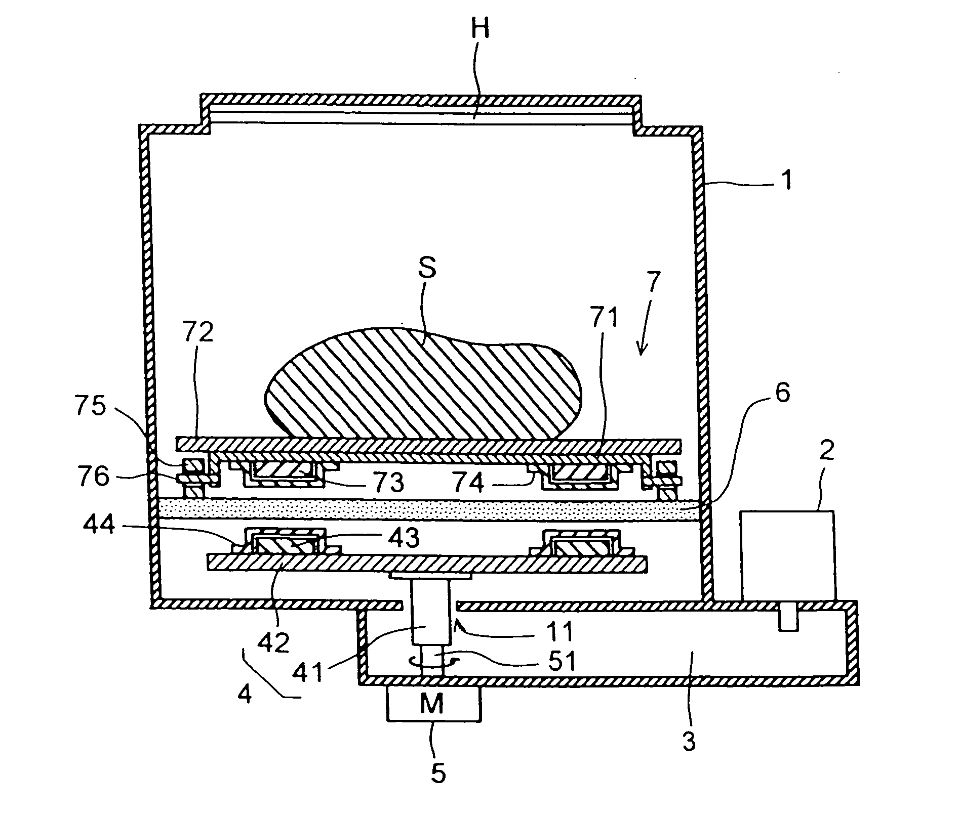
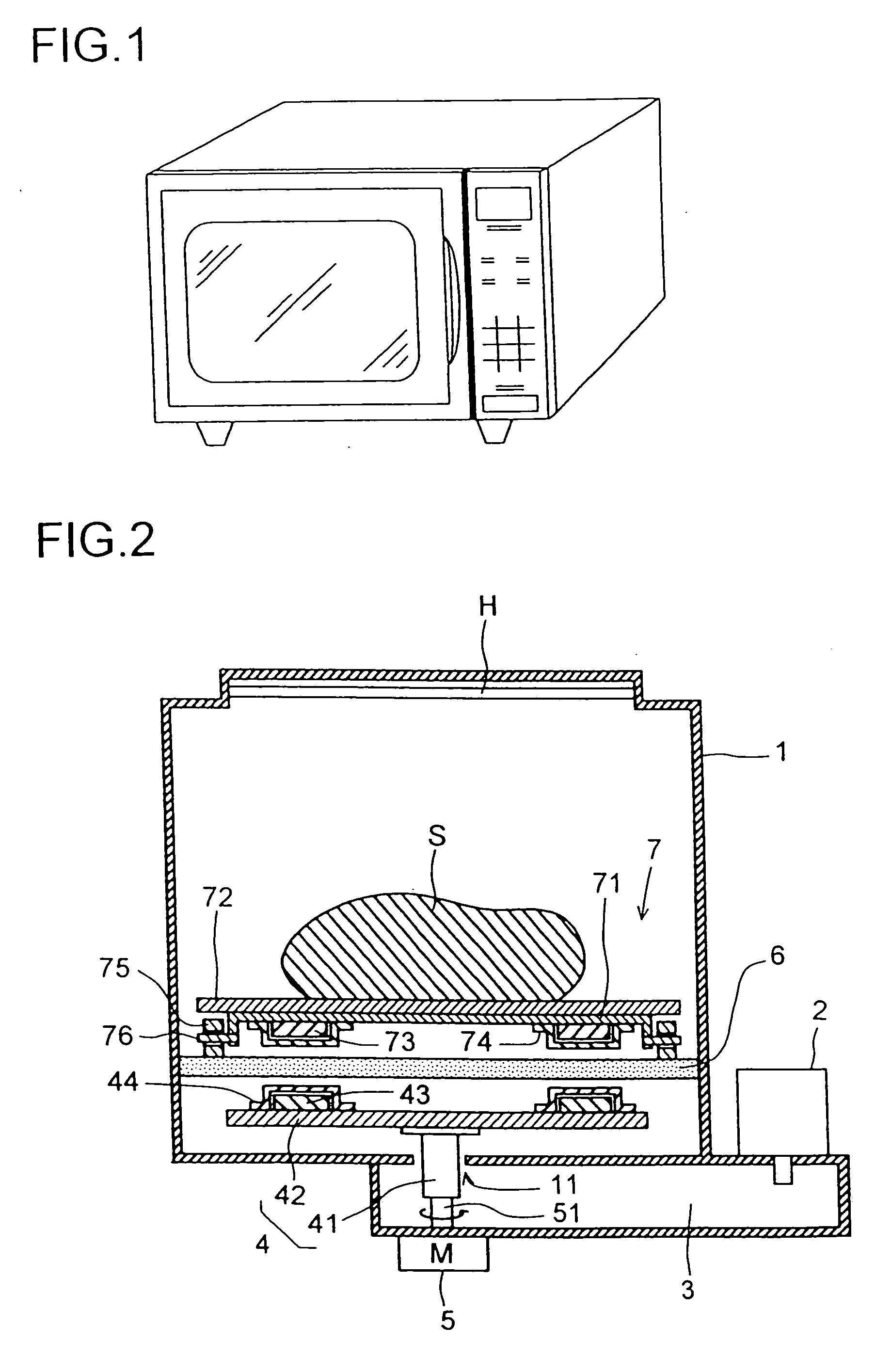
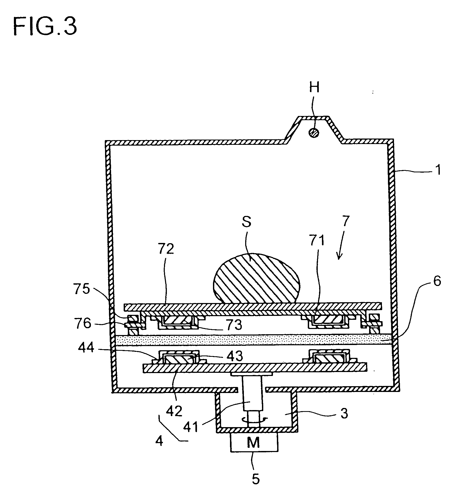
[0112] Next, the second embodiment will be described with reference to FIG. 29. If, in step S105 in FIG. 27 described earlier, the heating means is found not to be high-frequency heating (i.e., if it is found to be heater heating), then the flow proceeds to step S210 in FIG. 29. In this step, the antenna stop temperature S1 is set. Next, in step S220, the heating compartment temperature TS is sensed, and then the flow proceeds to step S230. In this step, whether or not the door is open is checked. If the door is found to be open, then, in step S240, the fourth relay switch SW4 is turned off to stop the rotation of the antenna 4. Then, the flow returns to step S230, where whether or not the door is open is checked again. So long as the door is found to be open, the operations in steps S230 and S240 are repeated. Thereafter, when the door 15 is found not to be open, the flow proceeds to step S250, where the fourth relay switch SW4 is turned on to rotate the antenna 4.

[0113] Next, in s...

third embodiment

[0114] Lastly, the third embodiment will be described with reference to FIG. 30. If, in step S105 in FIG. 27 described earlier, the heating means is found not to be high-frequency heating (i.e., if it is found to be heater heating), then the flow proceeds to step S310 in FIG. 30. In this step, the antenna stop time T1 is set. Next, in step S320, the stop timer is reset, and then the flow proceeds to step S330, where the stop timer is started to count time. Next, in step S340, whether or not the door is open is checked. If the door is found to be open, then, in step S341, whether or not the rotary stage 7 is being used is checked. If the rotary stage 7 is found to be used, then, irrespective of whether or not the timer has reached the antenna stop time T1, in step S350, the fourth relay switch SW4 is turned off to stop the rotation of the antenna 4. Then, the flow returns to step S340, where whether or not the door is open is checked again. So long as the door is found to be open and...


PUM


Abstract

A high-frequency heating apparatus comprises a heating chamber, a high-frequency generator, a waveguide, an antenna, a motor for rotating the antenna, and a stage (6) provided above and near the antenna to partition the heating chamber and made of dielectric. A rotary base on which an object to be heated is mounted is provided on the stage. A first magnet is provided to the antenna. A second magnet is provided on the rotary base at a place corresponding to the first magnet on the rotary base. By utilizing the magnetic coupling between the first and second magnets, the rotary base is rotated in synchronism with the rotation of the antenna. While maintaining the advantages of conventional antenna high-frequency heating apparatuses, the heating efficiency by grill heating or oven heating is enhanced, and minute heating uniformness is achieved.

Description

TECHNICAL FIELD [0001] The present invention relates to a high-frequency heating apparatus (hereinafter also referred to as a “microwave oven”), and more particularly to an antenna-type high-frequency heating apparatus. BACKGROUND ART [0002] Roughly speaking, uniform heating inside the heating compartment of a microwave oven is achieved by the use of a turntable, stirrer, or antenna. Now, a brief description will be given of how uniform heating is achieved by the use of each of these. Where a turntable is used, a heating target is placed on the turntable provided on the floor of the heating compartment, and the turntable is rotated. Thus, the high-frequency wave radiated into the heating compartment through an opening formed on a side wall surface or the ceiling surface thereof strikes the heating target uniformly from all directions, thereby heating it. This is the method that is currently most commonly used in microwave ovens. FIGS. 32 and 33 are a sectional view and a perspective...

Claims


Application Information

Patent Timeline
IPC IPC(8): H05B6/72H05B6/80
CPCH05B6/6411H05B6/72H05B6/725
Inventor KANEKO, FUMINORIKITAYAMA, HIROKIYAMAMOTO, YOSHIKAZUANDOH, YUZI
Owner SHARP KK
Why Eureka
Try Eureka