[0009] As a result, there is a problem that a relatively large amount of the waste portion including the aforementioned extension portion is simultaneously produced from the original material. On the other hand, the extension portion is to connect the feeding portion and the
peripheral wall section formed at a particular side of the partition face having no connecting wing. The
peripheral wall section and the feeding portion are separated so that the peripheral edge portion of the
metal mold corresponding to the peripheral wall section of the bulkhead extending the extension portion therefrom also performs as one
cutting edge of the cutter. In case, however, the peripheral edge of the
metal mold also performs as the
cutting edge while avoiding from producing waste of the material as possible, thickness of the peripheral edge of the
metal mold as the
cutting edge becomes thinner. This causes a
partial loss of the peripheral edge of the
metal mold when the bulkhead and the feeding portion are separated (as referred to FIG. 6). Therefore, the inventors have made investigations to develop a bulkhead having not only sufficient structural strength and rigidity, lighter weight, lower cost in manufacture, but also construction realizing reduction of waste of the materials and reduction of burden to the
metal mold.
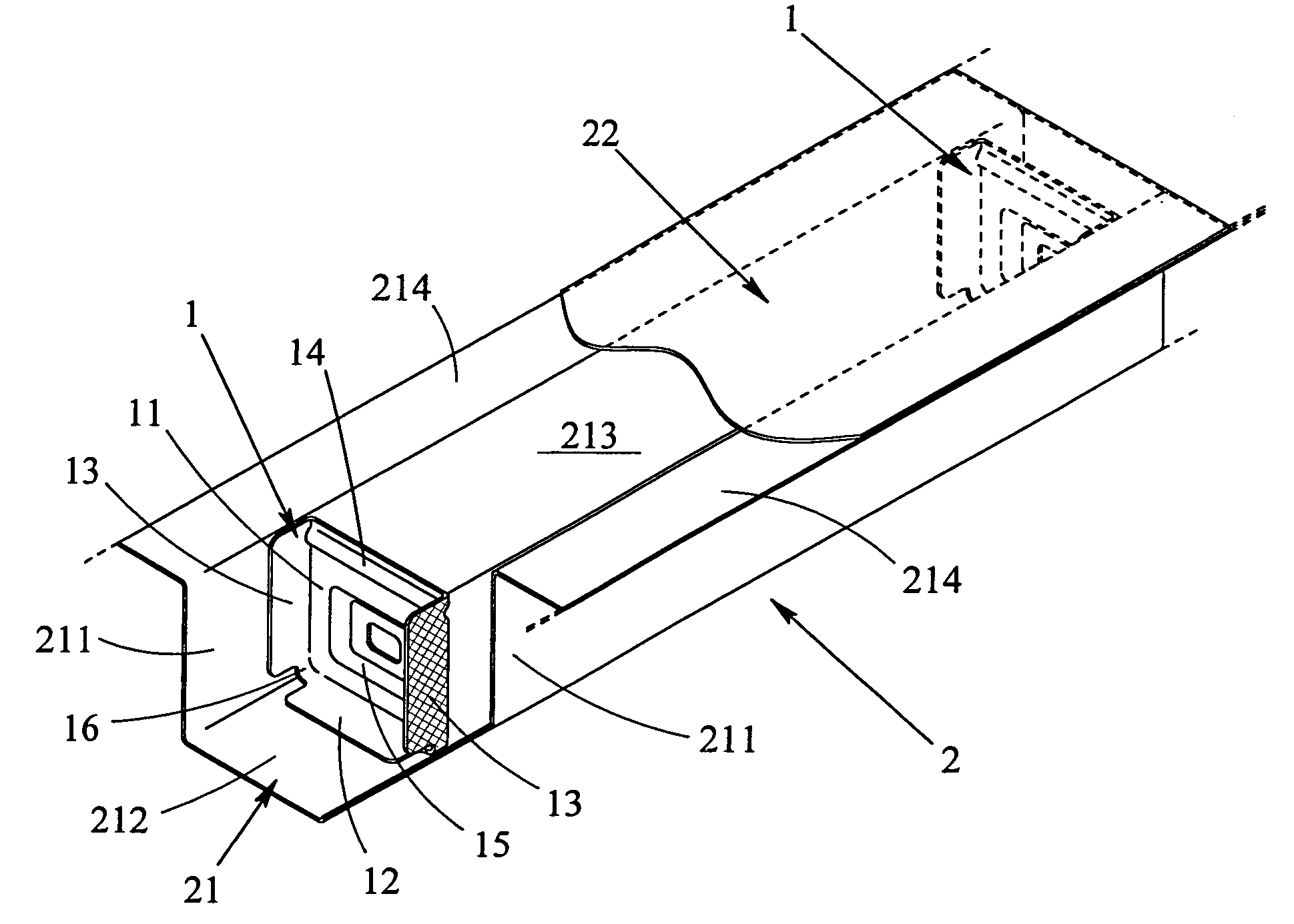
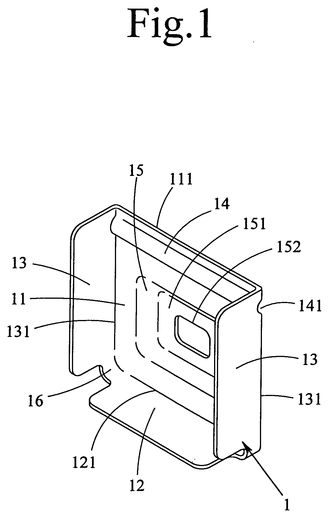
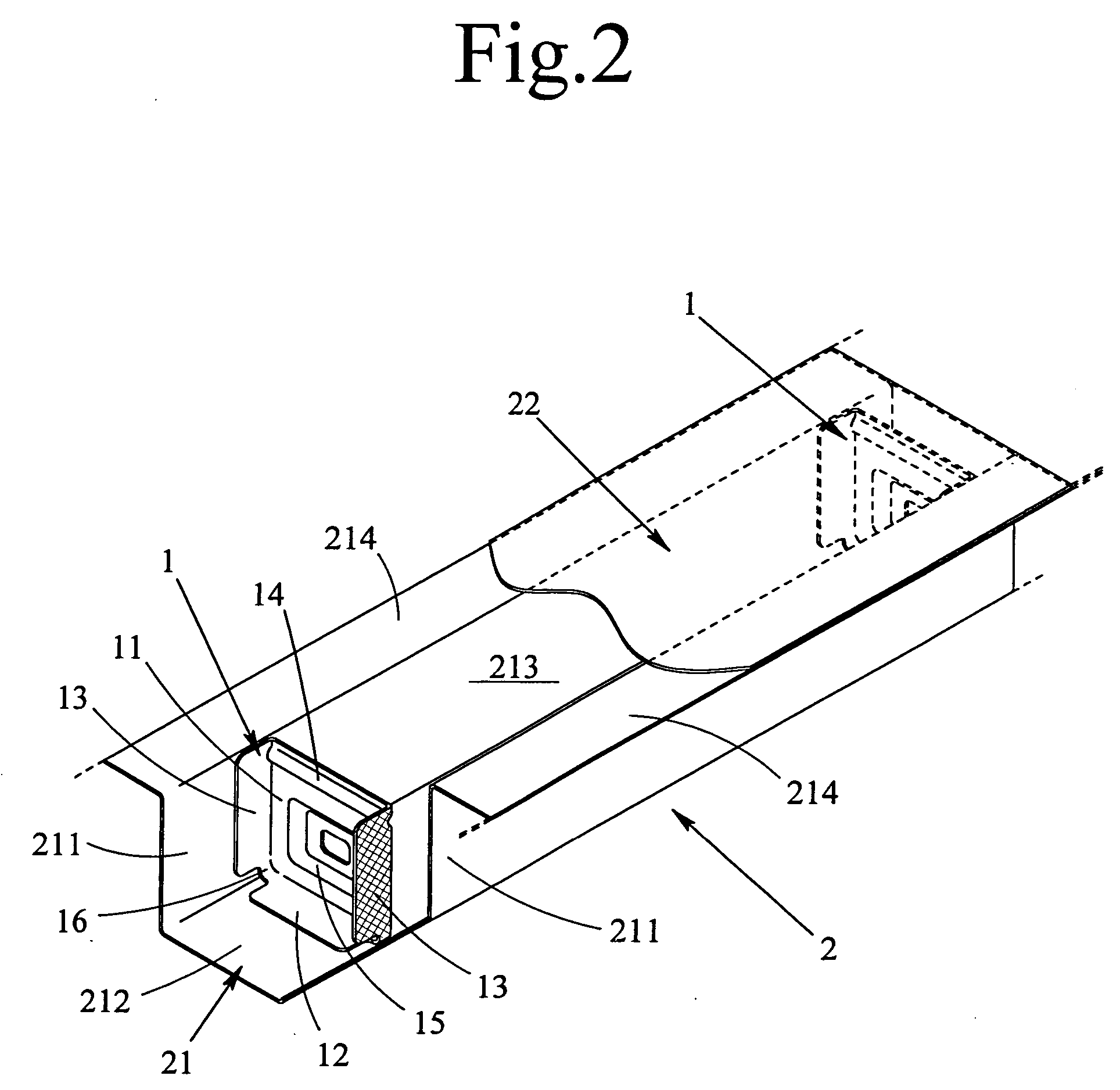
[0010] As a result of the investigations, the inventor has developed a bulkhead for raising strength and rigidity of vehicular frame members, which is an upright partition separating compartments of the vehicular frame member having a channel-shaped section, comprising: a partition face having an outer shape contoured to the sectional shape of the vehicular frame member; a plurality of connecting wings projected integrally from individual sides of the partition face except one specific side (hereinafter be referred to as an open edge) and then folded at the corresponding individual in the same direction, including a peripheral wall section having a C-shape formed by linking vicinities of the folded edges that are adjacent to each other; and a bead formed on the partition face near the open edge in that it is denting in the same direction of the connecting wings that are folded, and extending in parallel to the open edge through the opposed folded edges of the connecting wings. The individual connecting wings corresponding to the side faces of the main part of the vehicular frame member are fixed by inscribing and then
welding them with the individual side faces of the main part.
[0011] In the bulkhead of the invention, the bead, which is dented in the folded direction of the connecting wings and extending in parallel with the open edge between the opposed connecting wings, is formed on the partition face near the open edge, thereby to suppress or prevent the buckling, bending or deformation of the partition face or the folded edges. Specifically, the bead at first increases the modulus of section of the partition face to raise rigidity of the partition face thereby to suppress or prevent the buckling, bending or deformation of the partition face. Moreover, the bead extends between the opposed connecting wings to dent the edges of the individual connecting wings thereby to enhance the modulus of section of the edge. As a result, the higher rigidity of the partition face itself is further raised to suppress or prevent the buckling, bending or deformation of the edge. Moreover, the bead directly reinforces the vehicular frame member by performing also as a tension element extending between the opposed side faces of the main part of the vehicular frame member. The sectional shape of the aforementioned bead is arbitrary but is preferred to have such a semicircular sectional shape as can be easily formed by a press working.
[0012] Further, the bulkhead in the prior art demands the extension portion for absorbing the physical positional displacement, which is occurred during the press working, of the bulkhead from the feeding portion. On the contrary, the bulkhead of the invention needs no absorption of the physical positional displacement of the bulkhead from the feeding portion, because the bead can be formed utilizing by
ductility of the partition face. Therefore, in the present invention, it is effective sufficiently for adopting a simple connecting portion having no such extension portion disclosed in the prior art to connect the bulkhead and the feeding portion. Moreover, the bead causes not to construct thickness of a part of the
metal mold at least thinner to thereby avoiding the metal mold from becoming brittle, since the bead is not the side itself of the partition face but is formed as a
ridge on the inner side of the partition face in the same direction as the folded direction of the connecting wing. Especially in the metal mold of the prior art, the portion of the cutting edge is positioned at the upper edge of the peripheral wall section of the metal mold so that it rises to thin the metal mold partially. In the metal mold for shaping the bulkhead of the invention, on the contrary, no peripheral wall section exists between the open edge or the specific side of the partition face and the connecting portion so that the connecting portion is flatly connected with the open edge of the partition face without any steps. As a result, the cutting edge portion of the metal mold can be disposed at the same height as that of the partition face so that it is not necessary to form a thin and uprising cutting edge portion of the metal mold corresponding to the peripheral wall section of the bulkhead. Thus, according to the present invention, the sufficient strength of the metal mold can also be accomplished.
[0014] Next, the connecting wings fix the position of the partition face with respect to the main part of the vehicular frame member to
restrict the mutual positional relationship between the main part and the partition face, thereby suppressing or preventing inflection of the partition face. As a result, it may structure the connecting wings in the invention in that the connecting wings projected integrally from remaining sides except the open edge of the partition face are folded in the same direction at the folded edges as individual sides of the partition face. In addition, the connecting wings in the invention may provide the peripheral wall section that is formed by linking vicinities of the edges of all the connecting wings. The bulkhead in the prior art has the peripheral wall section in a shape of the closed ring enclosing the partition face. On the contrary, the invention provides the bulkhead comprising the bead that can raise rigidity of the partition face around the open edge is formed, and thereby to allow in use the peripheral wall section having a C-shape formed by the connecting wings.
[0015] The bulkhead of the invention has such an effect that it can be manufactured lightweight and inexpensive with less waste of the material while realizing sufficient structural strength and rigidity. At first, the sufficient structural strength and rigidity is given by the effect which is directly brought by the bead crossing the partition face in the sectional shape denting the individual folded edges of the opposed connecting wings. The bead not only raises the structural strength and rigidity of the partition face and the individual folded edges but also reinforces the main part of the vehicular frame member directly. Next, as to manufacturing of the bulkhead lightweight and inexpensive with less waste of the material, it is an effect obtained by eliminating the connecting wing positioned at the open edge of the partition face together with
elimination of the extension portion. In addition,
elimination of the peripheral wall section corresponding to the location of the open edge can also effect to manufacture the bulkhead in lighter weight and lower cost. Thus, the invention provides the bulkhead that can meet demands for being as a bulkhead.

