Plasma display apparatus
- Summary
- Abstract
- Description
- Claims
- Application Information
AI Technical Summary
Benefits of technology
Problems solved by technology
Method used
Image

Examples
second embodiment
[0072] Herein, the present invention may include a case where the horizontal width of the discharge cell is not linearly reduced but reduced by several stages as it goes to the upper portion or the lower portion, making the corner portions of the discharge cell have an irregular shape.
[0073] The first and second embodiments of the present invention may include a case where the discharge cell has such asymmetrical shape that the horizontal width of the upper portion of the discharge cell is not the same as that of the lower portion of the discharge cell.
third embodiment
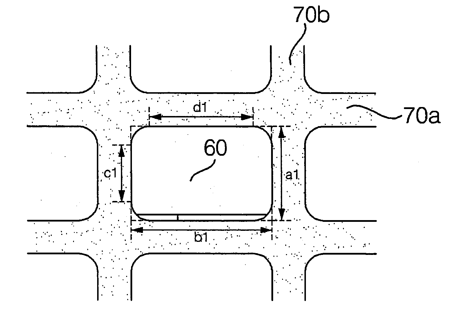
[0074] A plasma display apparatus in accordance with the present invention has a structure in that the horizontal width of the upper portion or the lower portion of the discharge cell is 90% or greater but smaller than 100% of that of the central portion of the discharge cell.
[0075] That is, with reference to FIGS. 5 to 7, the horizontal widths (d1, d2 and d3) of the upper portion or the lower portion of the discharge cell may be 90% or greater or smaller than 100% of that of the horizontal widths (b1, b2 and b3) of the central portion of the discharge cell.
[0076] In this case, if the horizontal width of the upper portion of the discharge cell is smaller than 90% of the horizontal width of the central portion in order to reduce the area of the discharge cell and increase the width of the barrier ribs, capacitance of the panel could be lowered but since the area of the discharge cell is reduced, the area of the phosphor layer coated inside the discharge cell is also reduced to cause...
sixth embodiment
[0090] A plasma display apparatus in accordance with the present invention has a structure in that the vertical width of the left portion or the right portion of the discharge cell is 80% or greater but smaller than 100% of that of the central portion of the discharge cell.
[0091] That is, with reference to FIGS. 5, 6 and 8, the vertical widths (c1, c2 and c4) of the upper portion or the lower portion of the discharge cell may be 80% or greater or smaller than 100% of that of the vertical widths (a1, a2 and a4) of the central portion of the discharge cell.
[0092] The reason for the limitation of the range is because, as stated above in the first and second embodiments of the present invention, if the area of the discharge cell is reduced, the panel capacitance would be lowered to advantageously reduce power consumption, but the panel luminance would be degraded.
[0093] In particular, if the vertical width of the upper portion of the discharge cell is smaller than 90% of the horizonta...
PUM
 Abstract
Description
Claims
Application Information
 - R&D
- Intellectual Property
- Life Sciences
- Materials
- Tech Scout
- Unparalleled Data Quality
- Higher Quality Content
- 60% Fewer Hallucinations
Browse by: Latest US Patents, China's latest patents, Technical Efficacy Thesaurus, Application Domain, Technology Topic, Popular Technical Reports.
© 2025 PatSnap. All rights reserved.Legal|Privacy policy|Modern Slavery Act Transparency Statement|Sitemap|About US| Contact US: help@patsnap.com