Solenoid driving apparatus

a solenoid driving and solenoid technology, applied in the direction of relays, emergency protective arrangements for limiting excess voltage/current, electric devices, etc., can solve the problem of difficult to incorporate this resistor into a semiconductor chip, and achieve the effect of inexpensive solenoid driving apparatus and very accurate control of current passing through the solenoid

Inactive Publication Date: 2006-05-11
SANKEN ELECTRIC CO LTD
View PDF8 Cites 6 Cited by
  • Summary
  • Abstract
  • Description
  • Claims
  • Application Information

AI Technical Summary

Benefits of technology

[0020] According to the present invention, the current passing through a solenoid can ...

Problems solved by technology

However, it is quite difficult to incorporate this resistor into a semiconductor chip becau...

Method used


Image

  • Solenoid driving apparatus
  • Solenoid driving apparatus
  • Solenoid driving apparatus

Examples


first embodiment

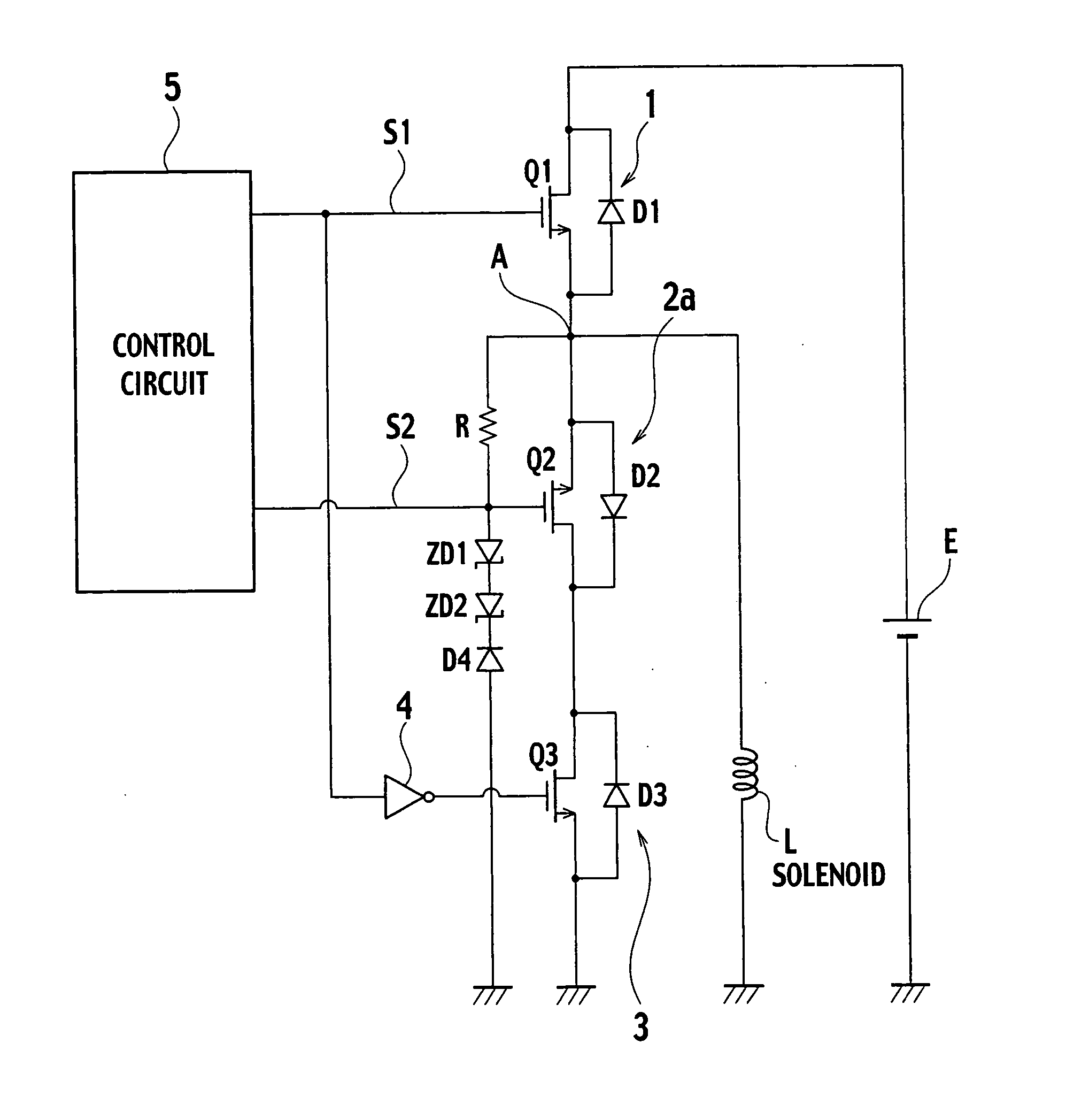
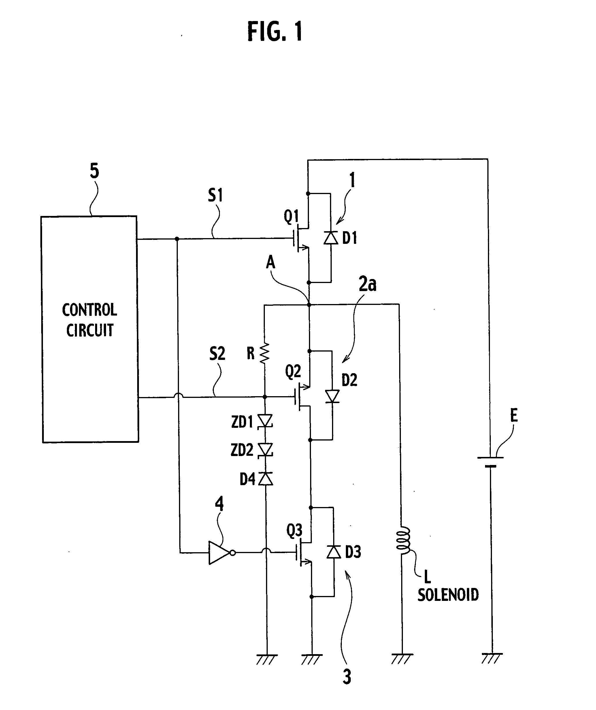
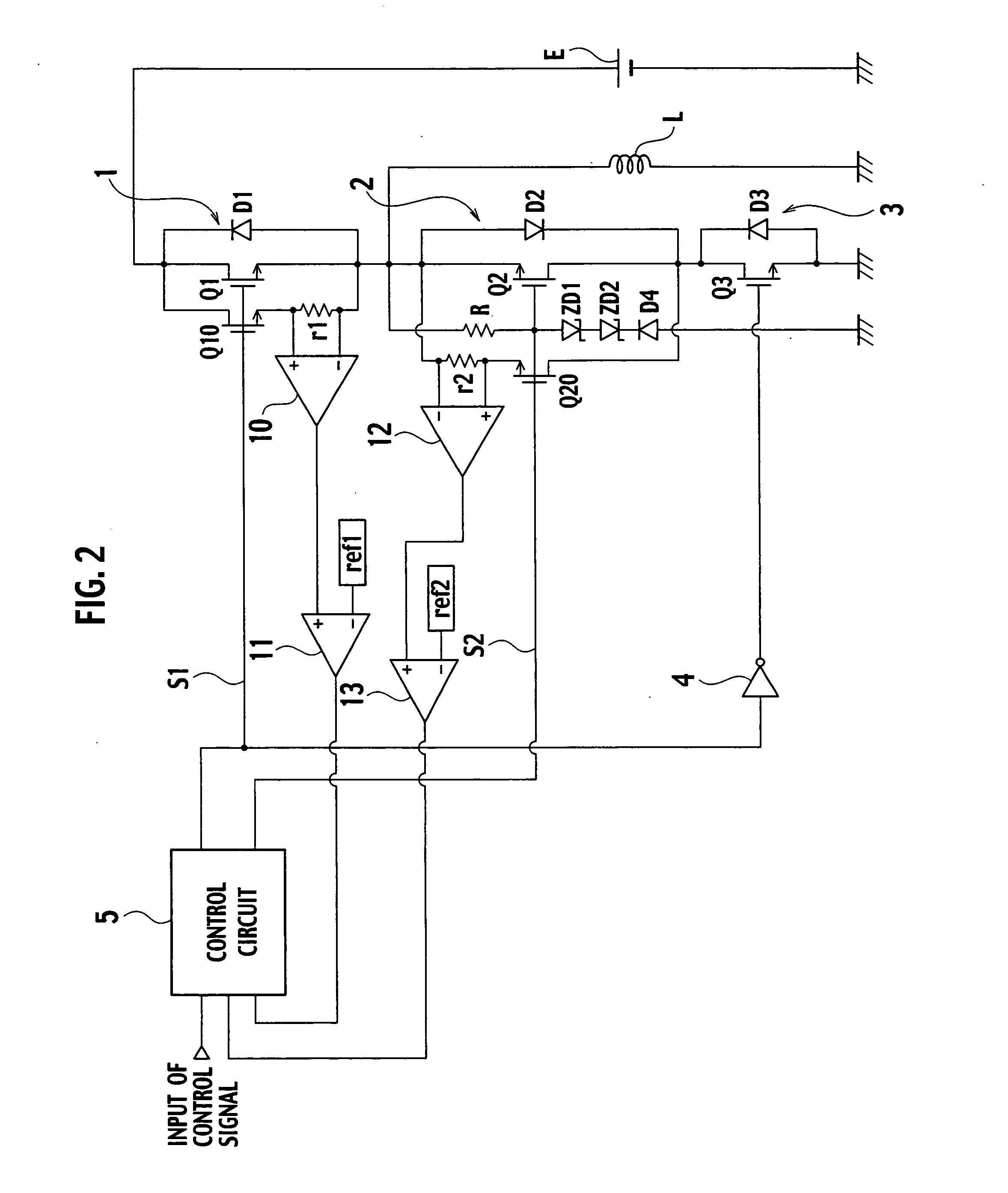
[0031]FIG. 3 shows a circuit structure of a solenoid driving apparatus according to a first embodiment of the present invention. The solenoid driving apparatus comprises a first current switching element 1, a second current switching element 2, a third current switching element 3, a battery E, a solenoid L, a resistor R, a zener diode ZD1, a zener diode ZD2, a diode D4, an inverter 4, a control circuit 5, a transistor Q20, a current detecting element r1, a differential amplifier 10, and gate drive circuits 20, 21, and 22. A loop current circuit of the present invention corresponds to the third current switching element 3. A current detector of the present invention comprises the transistor Q20, the current detecting element r1, and the differential amplifier 10.

[0032] The first current switching element 1 includes a transistor Q1 in the form of an N-channel MOSFET, and a diode D1 connected between the source and drain of the transistor Q1. The second current switching element 2 inc...

second embodiment

[0050] A solenoid driving apparatus according to a second embodiment of the present invention will be described below. The solenoid driving apparatus according to the second embodiment has the simplified configuration of the solenoid driving apparatus according to the first embodiment.

[0051]FIG. 5 shows the circuit structure of the solenoid driving apparatus according to the second embodiment of the present invention. The solenoid driving apparatus is characterized such that a diode D5 is employed instead of the third current switching element 3 which is used as the loop current circuit in the solenoid driving apparatus according to the first embodiment, and also a hysteresis comparator (Schmitt circuit) OP1 is employed instead of the differential amplifier 10 in order to send an output of the hysteresis comparator OP1 directly (not bypassing the control circuit 5) to the gate drive circuit 20.

[0052] Operations of the solenoid driving apparatus according to the second embodiment w...


PUM


Abstract

A solenoid driving apparatus that drives a solenoid by intermittently supplying an exciting current comprises a first current switching element turned ON and OFF so as to switchably allow and block passage of the exciting current supplied to the solenoid L, a loop current circuit 3 being connected to the first current switching element and passing a loop current caused by stored energy in the solenoid when the supply of the exciting current to the solenoid is stopped by the first current switching element, and a second current switching element being disposed between the solenoid and a junction of the first current switching element and the loop current circuit, and being turned ON and OFF so as to switchably allow and block passage of the exciting current and the loop current.

Description

BACKGROUND OF THE INVENTION [0001] The present invention relates to a solenoid driving apparatus for driving a solenoid that is used, for example, for various controls of automobiles. [0002] As a solenoid driving apparatus for driving a solenoid, a constant-current driving circuit for inductive loads has been known, which has semiconductor integrated circuits for driving inductive loads, as disclosed in Japanese Patent Application Laid-Open No. 2001-117651. [0003]FIG. 1 shows a typical circuit of a conventional solenoid driving apparatus. This solenoid driving apparatus includes a first current switching element 1, a second current switching element 2a, a third current switching element 3, a battery E, a solenoid L, a resistor R, zener diodes ZD1 and ZD2, a diode D4, an inverter 4, and a control circuit 5. [0004] The first current switching element 1 has a transistor Q1 in the form of an N-channel MOSFET, and a diode D1 connected between the source and drain of the transistor Q1. Th...

Claims


Application Information

Patent Timeline
IPC IPC(8): H01H47/00
CPCH01H47/325H02H9/047
Inventor SATOH, KIYOKATSUKATOH, JUNICHI
Owner SANKEN ELECTRIC CO LTD
Why Eureka
Try Eureka