Flame simulating assembly

a technology of simulating assembly and flame, which is applied in the field of simulating assembly, can solve the problems of affecting the simulation effect, affecting the effect of simulation,

Inactive Publication Date: 2006-05-18
DIMPLEX NORTH AMERICA
View PDF99 Cites 95 Cited by
  • Summary
  • Abstract
  • Description
  • Claims
  • Application Information

AI Technical Summary

Benefits of technology

[0026] In another of its aspects, the controller is adapted

Problems solved by technology

However, the use of a cover or a (partially translucent shell) such as the cover disclosed in Dewey to imitate burning solid combustible fuel has some disadvantages.
Because it is evident from even a cursory observation of this type of prior art simulated fuel bed that the raised parts (i.e., simulated logs) are actually formed integrally with the simulated ember bed part of the shell, this type of simulated fuel bed tends to detract from the simulation effect sought.
Another disadvantage of the prior art results from characteristics of the typical light source which is intended to provide light which imitates the light produced by glowing embers in a real fire.
However, the characteristics of light from embers are somewhat different from those of light from flames.
For instance, embers generally tend to glow, and pulsate, but flames tend to flicker, and move.
Because of these differences, attempts in the prior art to use the same light source to provide a flame simulation effect and a burning ember simula

Method used


Image

  • Flame simulating assembly
  • Flame simulating assembly
  • Flame simulating assembly

Examples


Embodiment Construction

)

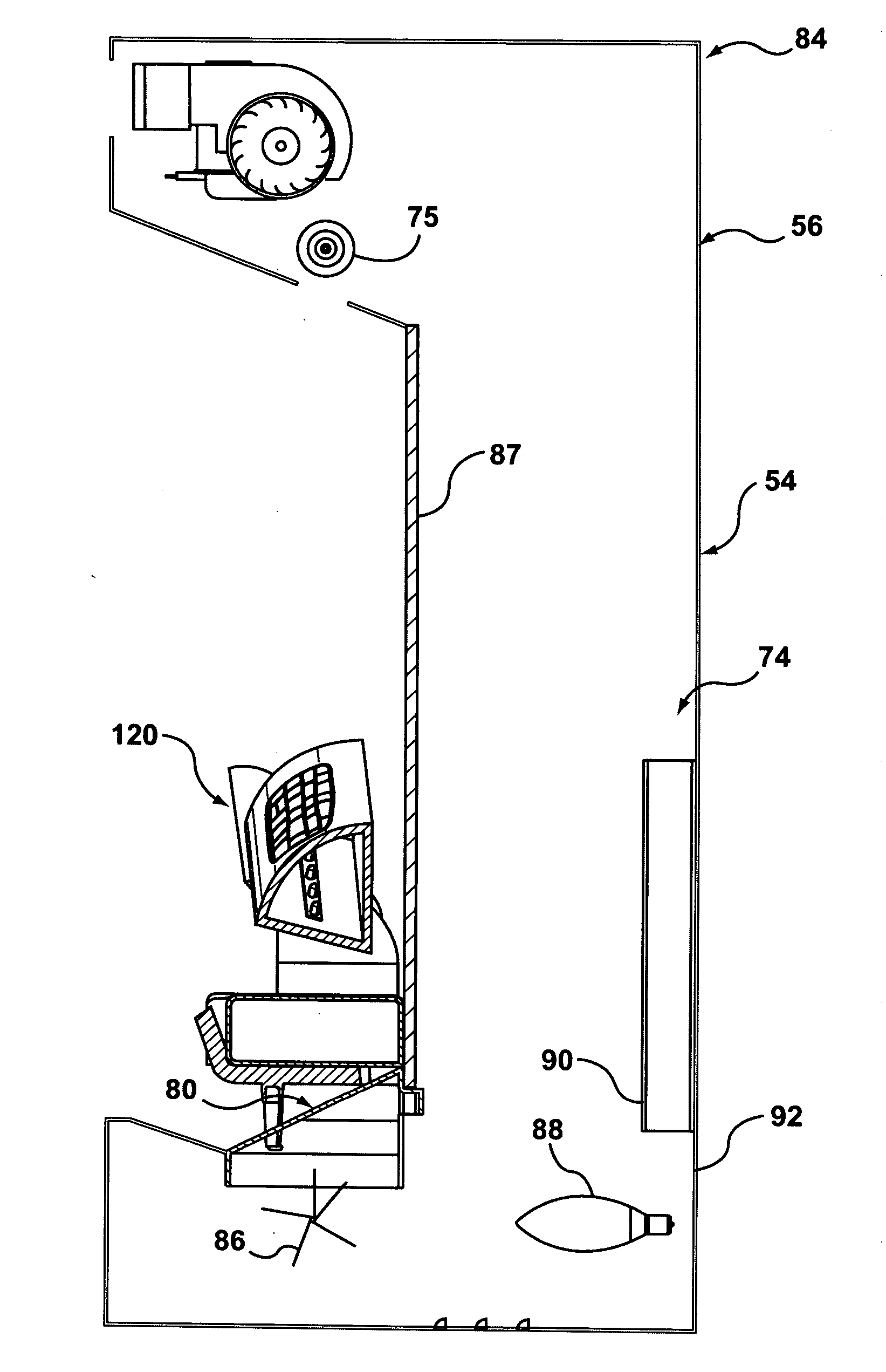
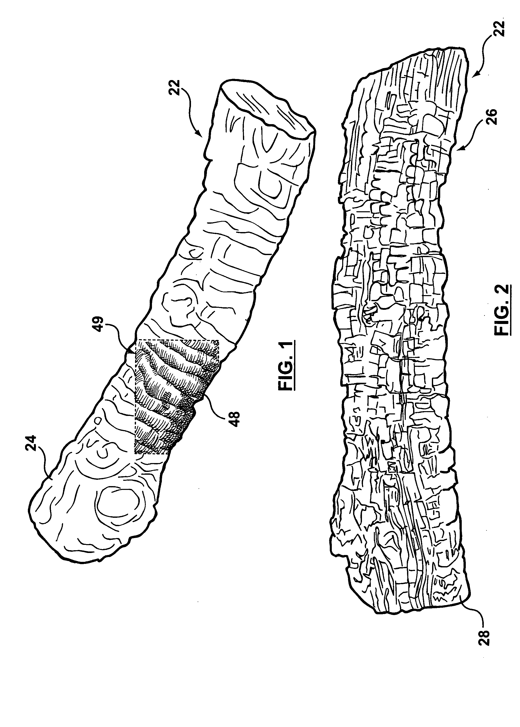
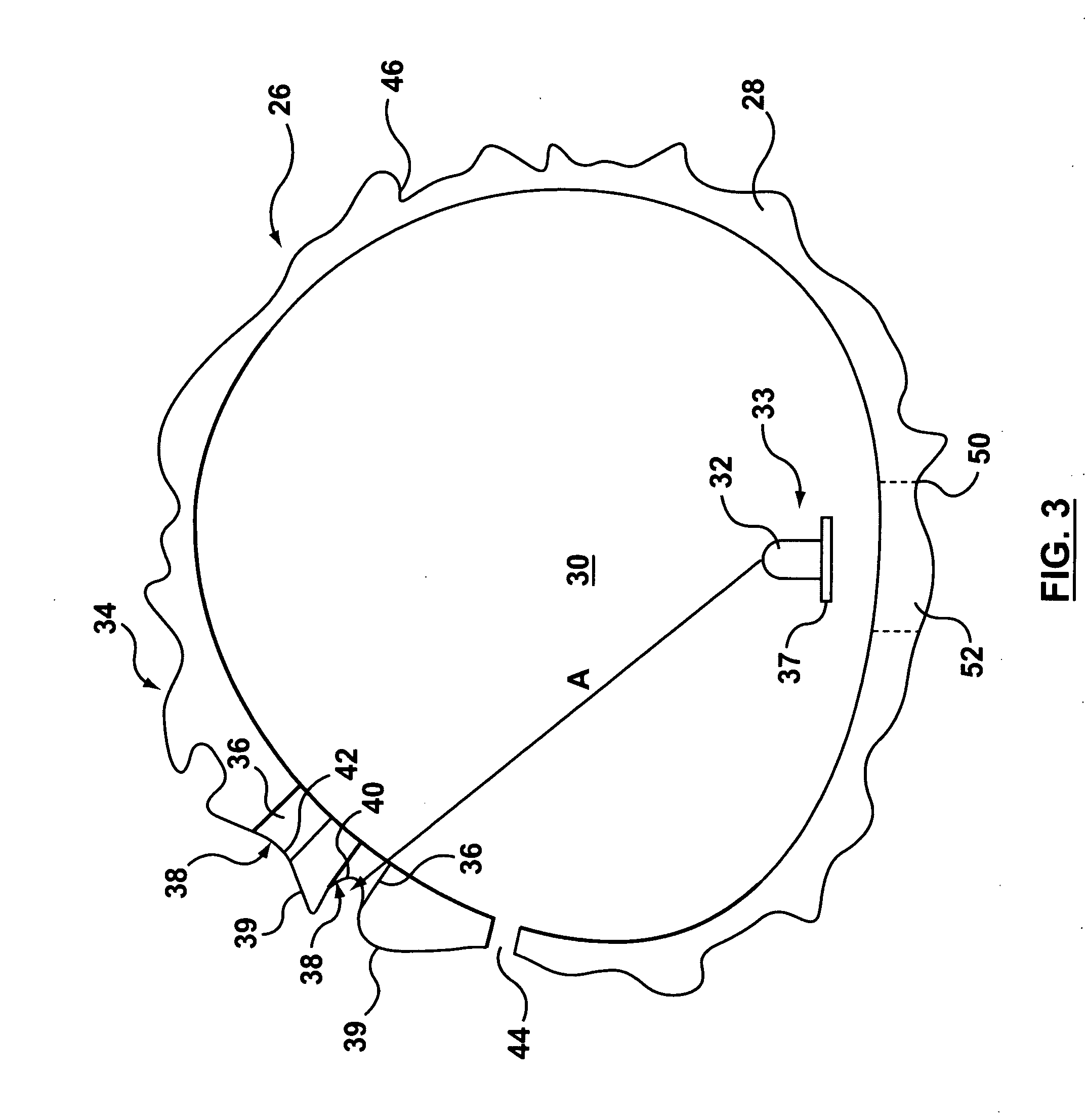
[0054] Reference is first made to FIGS. 1-7 to describe an embodiment of a simulated fuel bed in accordance with the invention indicated generally by the numeral 20 (FIGS. 4A, 4B). The simulated fuel bed 20 is for simulating a solid combustible fuel burning, and partially consumed, in a natural fire. Preferably, the simulated fuel bed 20 includes a number of simulated solid combustible fuel elements 22 (FIGS. 7, 8), for simulating fuel elements which have not been consumed by the fire, or have only partially been consumed. Each simulated combustible fuel element 22 has a body 24 which is colored and formed to resemble an entire solid combustible fuel element, as will be described.

[0055] As shown in FIGS. 4A, 4B and 5, the elements 22 are preferably arranged in a pile 25, for instance, to imitate a pile of wooden logs in a natural fire. It will be understood that the simulated fuel elements 22 may, in the alternative, be formed and colored to resemble pieces of coal. Where the simu...


PUM


Abstract

A simulated fuel bed for simulating a combustible fuel in a fire. The simulated fuel bed includes a plurality of simulated combustible fuel elements, including one or more light-producing simulated combustible fuel elements. A body of the light-producing simulated combustible fuel element has one or more cavities therein, and one or more light sources positioned to direct light therefrom inside the cavity. The body includes an exterior surface and one or more light-transmitting parts extending between the cavity and the exterior surface. The light-transmitting part is positioned in a path of light from the light source. The light from the light source is transmittable through the light-transmitting part to the exterior surface for simulating glowing embers of the combustible fuel.

Description

[0001] This application claims the benefit of U.S. Provisional Application No. 60 / 628,109, filed Nov. 17, 2004.FIELD OF THE INVENTION [0002] This invention is related to a flame simulating assembly for providing images of flames. BACKGROUND OF THE INVENTION [0003] Various types of flame simulating assemblies, such as electric fireplaces, are known. Many of the prior art flame simulating assemblies include a simulated fuel bed which resembles a burning solid combustible fuel, as well as embers and ashes resulting from the combustion. For example, U.S. Pat. No. 566,564 (Dewey) discloses an electric heating apparatus with a cover (B′) which “is made . . . of a transparent or semitransparent material” (p. 1, lines 50-52). The cover is “fashioned or colored” so that it resembles coal or wood “in a state of combustion when light is radiated through it” (p. 1, lines 53-57). [0004] However, the use of a cover or a (partially translucent shell) such as the cover disclosed in Dewey to imitate...

Claims


Application Information

Patent Timeline
IPC IPC(8): G09F19/00
CPCF24B1/1808F24C7/004G09F19/12B05D5/00
Inventor HESS, KRISTOFFERCHAMP, MARTYNJACH, MICHAELSTINSON, KELLY
Owner DIMPLEX NORTH AMERICA
Why Eureka
Try Eureka