Method and system for influencing the quantity of exhaust gas recirculated in a pressure charged internal combustion engine

a pressure-charged internal combustion engine and quantity technology, applied in the direction of machines/engines, mechanical equipment, non-fuel substance addition to fuel, etc., can solve the problems of reducing the power provided, adversely affecting efficiency, and achieving discernible increase in power output, so as to increase the quality and flexibility of pressure charging and high boost pressure

Inactive Publication Date: 2006-05-18
FORD GLOBAL TECH LLC
View PDF13 Cites 27 Cited by
  • Summary
  • Abstract
  • Description
  • Claims
  • Application Information

AI Technical Summary

Benefits of technology

[0034] The present invention overcomes the known disadvantages inherent in the state of the art and which is, in particular, capable of achieving simultaneously high exhaust gas recirculation rates and high boost pressures, particularly in the partial load range.
[0080] Advantageous embodiments of the method include those in which the quantity of recirculated exhaust gas is reduced through a reduction of the exhaust gas back-pressure in the first exhaust line.

Problems solved by technology

Whereas, a mechanical supercharger obtains all of the energy needed to drive it from the internal combustion engine, thereby reducing the power provided and adversely affecting efficiency.
The design of the exhaust-gas turbocharger presents problems in that a discernible increase in the power output is sought in all engine speed ranges.
In the state of the art, however, a pronounced loss of torque is observed once the engine speed drops below a specific number of revolutions.
This effect is undesirable, since even in the lower engine speed range the driver expects a correspondingly high torque compared to a naturally aspirated engine of identical power output.
The so-called turbo lag at low engine speeds, therefore, ranks as one of the most serious disadvantages of exhaust turbocharging.
As a result, towards the lower engine speeds the boost pressure ratio also falls, which results in the loss of torque.
The fall in the boost pressure can be counteracted by a reduction of the turbine cross-section and the associated rise in the turbine pressure ratio, which, however, leads to disadvantages at high engine speeds.
This ultimately counteracts the loss of torque only to a limited extent and the loss of torque is shifted further towards the lower engine speeds.
There are, moreover, limits to this approach, that is to say the reduction of the turbine cross-section, since the desired pressure charging and power increase are supposed to be possible without restriction and to the desired extent even at high engine speeds.
This method, however, as already described above, has the disadvantage that the pressure charging performance is inadequate at higher engine speeds.
It is in principle, also, possible to design the turbine with a small turbine cross-section in conjunction with charge air relief, this variant seldom being used owing to the energy disadvantages of charge air relief, that is to say the adverse effect on the overall efficiency, and the fact that existing compressors can reach their delivery limit and are therefore no longer able to supply the desired output.
However, this does not fully exploit the scope for boosting power by means of exhaust gas turbocharging.
The disadvantages here are the high build costs and the sluggish behavior in response to engine speed changes.
This results, however, in a conflict when operating an internal combustion engine with exhaust gas turbocharging and the simultaneous use of exhaust gas recirculation, since the recirculated exhaust gas is drawn from the exhaust line upstream of the turbine.
In addition to the falling boost pressure, other problems can arise in the operation of the compressor with regard to the pumping limit of the compressor.
This leads to increased soot formation, especially during acceleration, because the inertia of the rotor of the exhaust-gas turbocharger the quantity of fuel often increases more rapidly than the fresh air fed to the cylinders.

Method used


Image

  • Method and system for influencing the quantity of exhaust gas recirculated in a pressure charged internal combustion engine
  • Method and system for influencing the quantity of exhaust gas recirculated in a pressure charged internal combustion engine
  • Method and system for influencing the quantity of exhaust gas recirculated in a pressure charged internal combustion engine

Examples


first embodiment

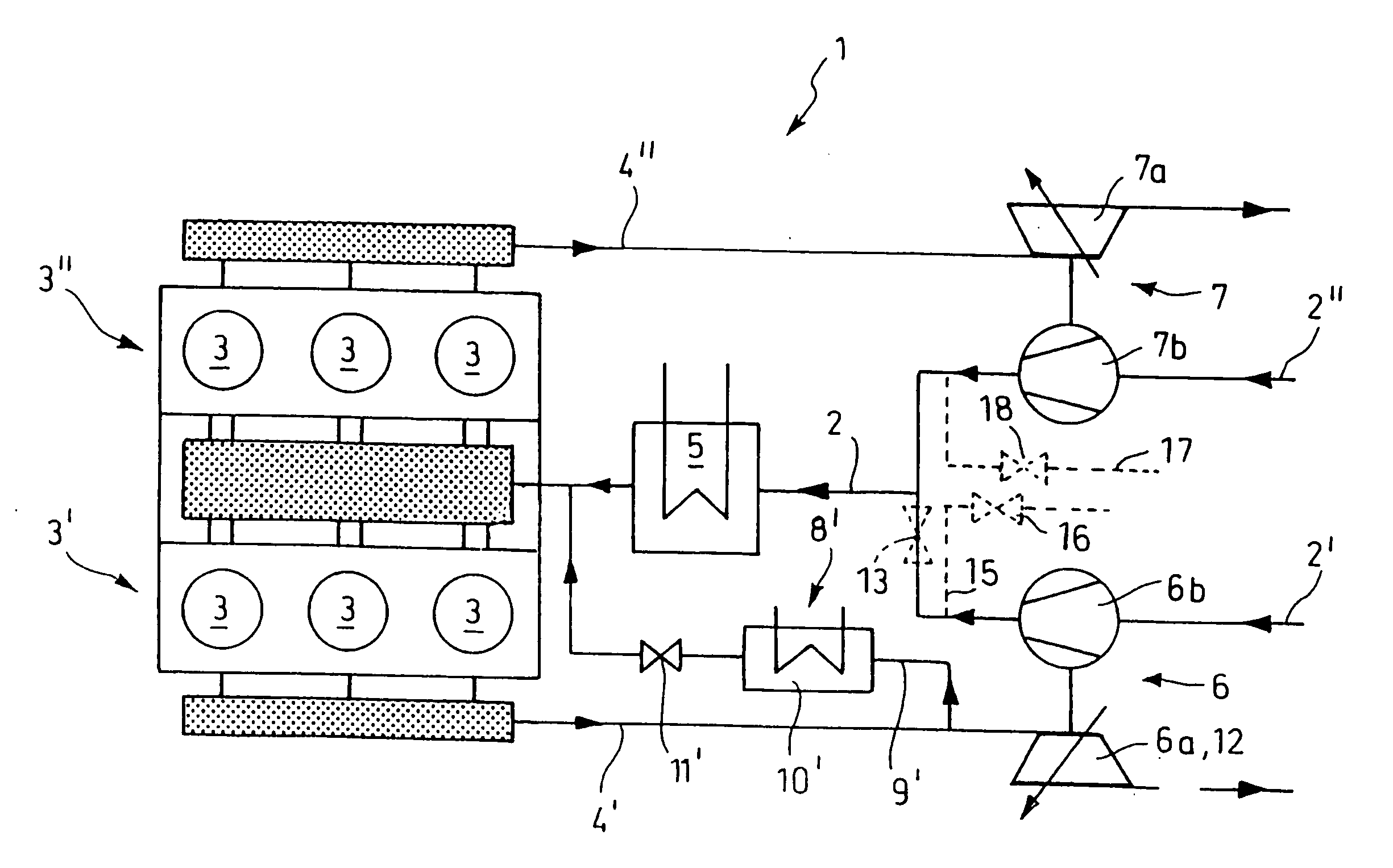
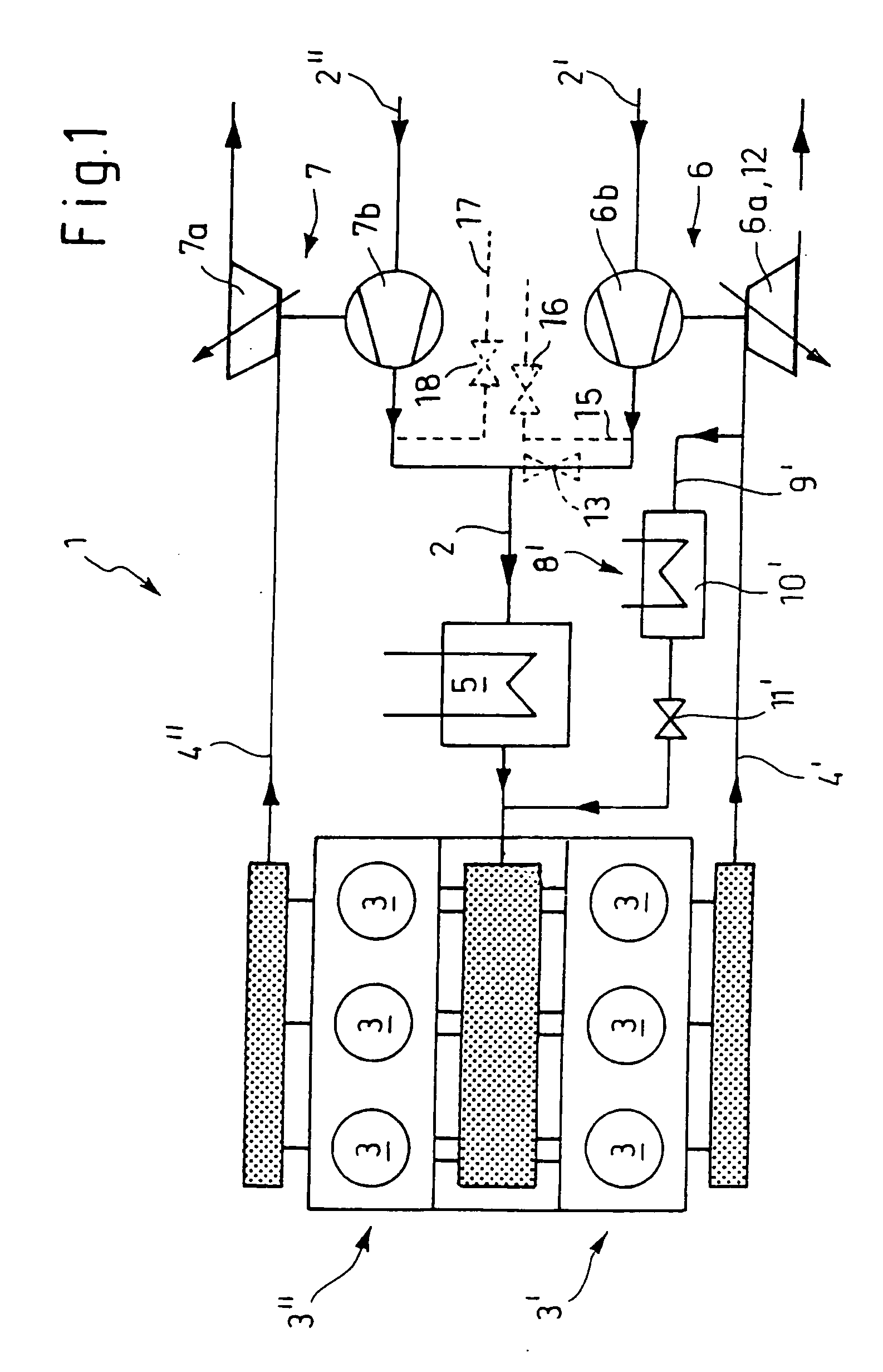
[0093]FIG. 1 shows the pressure charged internal combustion engine 1, taking a six-cylinder V-engine as an example. The cylinders 3 of the internal combustion engine 1 are divided into two groups of cylinders 3′, 3″, which each have a separate exhaust line 4′, 4″, which is in each case not connected to the other exhaust line 4′, 4″.

[0094] Two exhaust-gas turbochargers 6, 7 connected in parallel are provided, the first turbine 6a of the first exhaust-gas turbocharger 6 being arranged in the first exhaust line 4′ of the first group of cylinders 3′ and the second turbine 7a of the second exhaust-gas turbocharger 7 being arranged in the second exhaust line 4″ of the second group of cylinders 3″.

[0095] The compressors 6b, 7b coupled to these turbines 6a, 7a are likewise arranged in separate intake lines 2′, 2″, which downstream of the compressors 6b, 7b converge to form an intake manifold 2 and which serve to supply the internal combustion engine 1 with fresh air or fresh mixture.

[0096...

second embodiment

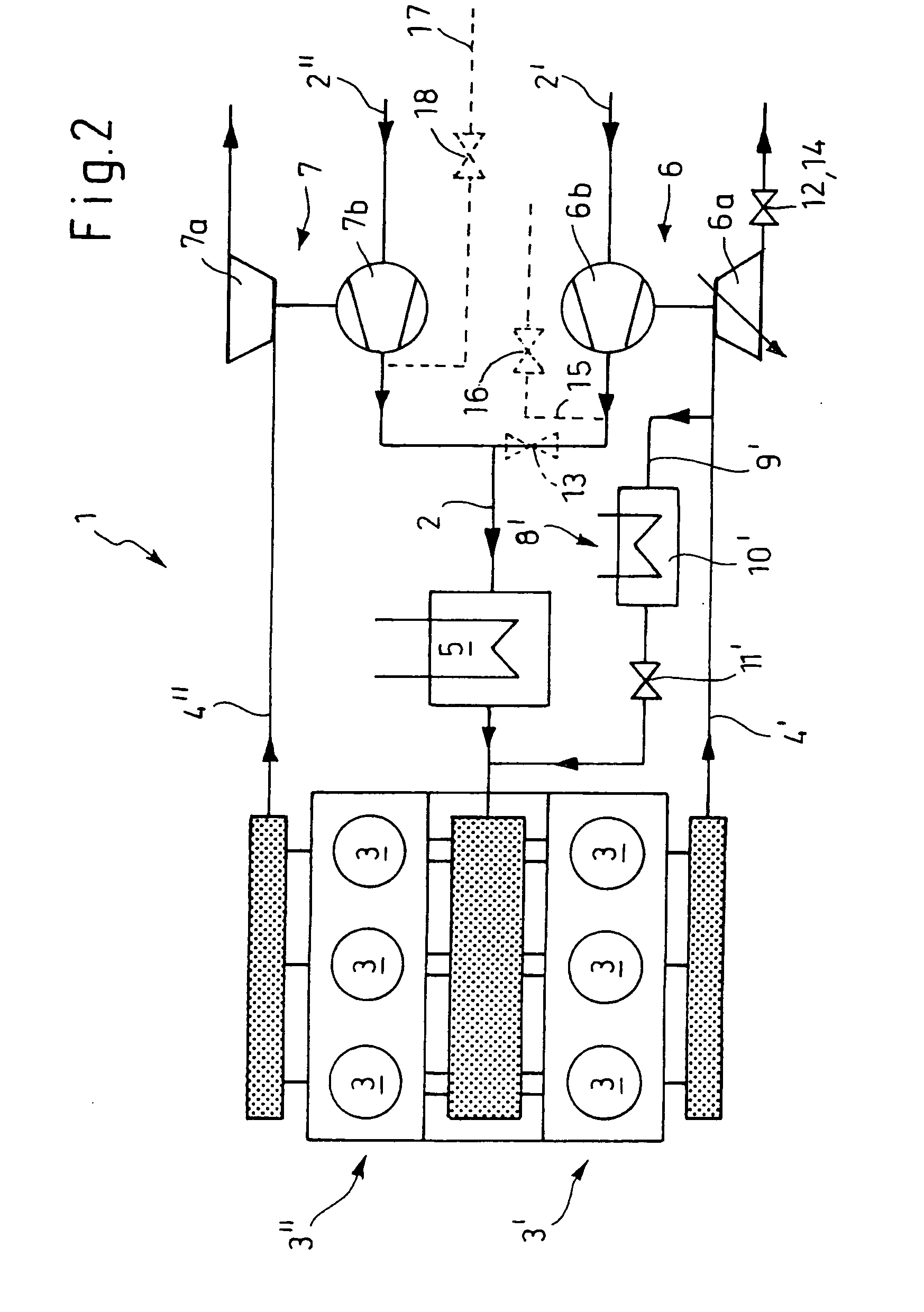
[0106]FIG. 2 shows a schematic representation of the pressure charged internal combustion engine 1. Only those aspects distinguishing it from the embodiment represented in FIG. 1 will be discussed, for which reason reference will otherwise be made to FIG. 1. The same reference numerals have been used for the same components.

[0107] In contrast to the embodiment represented in FIG. 1, the second turbine 7a in the internal combustion engine 1 represented in FIG. 2 is designed with a fixed, that is to say a non-variable turbine geometry. In contrast to the embodiment of the turbine with variable turbine geometry (VTG) previously described, the design principle here dispenses with any control. Overall, this embodiment in particular has cost advantages.

[0108] A further difference compared to the embodiment according to FIG. 1 is that a separate shut-off element 14 is provided in the first exhaust line 2′ downstream of the first turbine 6a to influence the exhaust gas back-pressure. The s...

third embodiment

[0109]FIG. 3 shows a schematic representation of the pressure charged internal combustion engine 1. Only those aspects distinguishing it from the embodiment represented in FIG. 2 will be discussed, for which reason reference will otherwise be made to FIG. 2. The same reference numerals have been used for the same components.

[0110] In contrast to the embodiment represented in FIG. 2 in the internal combustion engine 1 represented in FIG. 3 the first turbine 6a is likewise designed with a fixed, that is to say a non-variable turbine geometry, which again has cost advantages owing to the more economical type of turbine and to the absence of an expensive control.


PUM


Abstract

The invention relates to a pressure charged internal combustion engine (1) having at least two cylinders (3), configured to form two groups (3′, 3″) each with a separate exhaust line (4′, 4″), and two exhaust-gas turbochargers connected in parallel (6, 7), a first turbine (6a) being arranged in the exhaust line (4′) of the first group (3′) and a second turbine (7a)) being arranged in the exhaust line (4″) of the second group (3 ″) and the compressors (6b, 7b) coupled to these turbines (6a, 7a) arranged in separate intake lines (2′, 2″), which converge to form an intake manifold (2) to supply the internal combustion engine (1) with fresh air. The invention relates to a method of influencing the quantity of exhaust gas recirculated by a pressure charged internal combustion engine (1). The pressure charged internal combustion engine is capable of achieving high exhaust gas recirculation rates and high boost pressures simultaneously.

Description

FIELD OF THE INVENTION [0001] The invention relates to a method of influencing the quantity of exhaust gas recirculated by a pressure charged internal combustion engine in a pressure charged internal combustion engine having two turbochargers. BACKGROUND OF INVENTION [0002] In recent years there has been a trend towards small, highly pressure charged engines, the pressure charging primarily being a method of boosting the power output, in which the air needed for the engine combustion process is compressed. The economic importance of these engines for the automobile manufacturing industry steadily continues to increase. [0003] Pressure charging, meaning pressurizing the intake gases, is generally achieved by the use of an exhaust-gas turbocharger, in which a compressor and a turbine are arranged on the same shaft, the hot exhaust gas flow being delivered to the turbine, where it expands, releasing energy and causing the shaft to rotate. The energy which the exhaust gas flow delivers ...

Claims


Application Information

Patent Timeline
Patent Type & Authority Applications(United States)
IPC IPC(8): F02D23/00F02B33/44F02M25/07
CPCF01N13/107F02B29/0406F02B37/007F02B37/16F02B37/18F02B37/22F02B37/24F02M25/0711F02M25/0732F02M25/0744Y02T10/121Y02T10/144F02M26/08F02M26/24F02M26/38Y02T10/12
Inventor SCHORN, NORBERT A.KINDL, HELMUT M.SPAEDER, UWE R.STALMAN, ROB
Owner FORD GLOBAL TECH LLC
Why Eureka
Try Eureka