Very low temperature refrigerator

a refrigerator and very low temperature technology, applied in the field of cryogenic refrigerators, can solve the problems of irregularity in the refrigerating ability of refrigerator units, inability to perform temperature adjustment of respective refrigerator units,

Active Publication Date: 2006-05-18
SUMITOMO HEAVY IND LTD
View PDF1 Cites 42 Cited by
  • Summary
  • Abstract
  • Description
  • Claims
  • Application Information

AI Technical Summary

Benefits of technology

[0019] The present invention further provides a cryogenic measuring apparatus characterized by comprising a temperature sensor for detecting a temperature of any optional position of the cryogenic measuring apparatus; and a controller for controlling the means for varying the frequency of the motor driving the intake/exhaust valve managing the intake/exhaust cycle time of the refrigerator unit in accordance with an output of the temperature sensor, thereby achieving the above first object as well as the above second and third objects.
[0020] In addition, the present invention provides a simple liquefaction apparatus characterized by comprising the above-mentioned refrigerator unit or the above-mentioned cryogenic refrigerator, thereby achieving the above first object as well as the above second and third objects.
[0021] The present invention further provides a simple liquefaction apparatus characterized by comprising a temperature s

Problems solved by technology

However, since the heater is used in an extremely low temperature environment, its reliability is low, resulting in a low insulation which causes an electric leak and hence some troubles such as an emergency shut down due to such an electric leak.
Although this method is effective when a single refrigerator unit is operated by a single compressor unit, when a plurality of refrigerator units are operated by one or more compressor units, there had been a problem that it was impossible to perform the temperature adjustment of the respec

Method used


Image

  • Very low temperature refrigerator
  • Very low temperature refrigerator
  • Very low temperature refrigerator

Examples


second embodiment

[0037] Next, the present invention will be described.

first embodiment

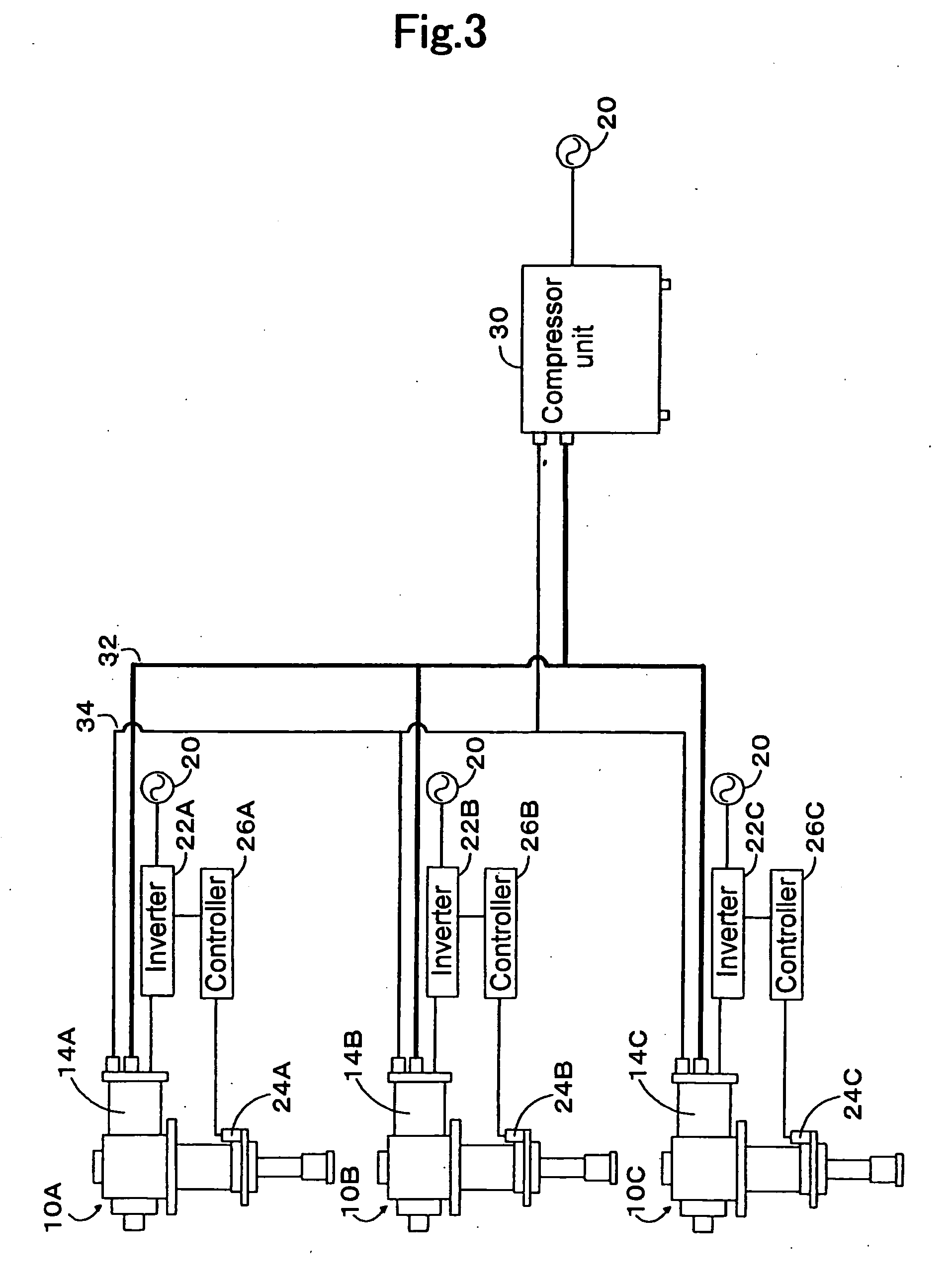
[0038] The present embodiment, as shown in FIG. 3, is formed by applying the present invention to the case where a single compressor unit 30 is used to run refrigerator units 10A, 10B, and 10C of three second-stage G-M cycle refrigerators. Similar to the first embodiment, the refrigerator units 10A, 10B, and 10C are provided with inverters 22A, 22B, and 22C, temperature sensors 24A, 24B, and 24C, as well as controllers 26A, 26B, and 26C, respectively.

[0039] In the present embodiment, since each refrigerator unit can control an intake / exhaust cycle time in a manner such that the temperature of the first-stage low-temperature unit can reach a target value, it is possible to eliminate an irregularity among these refrigerator units.

third embodiment

[0040] Next, the present invention will be described.

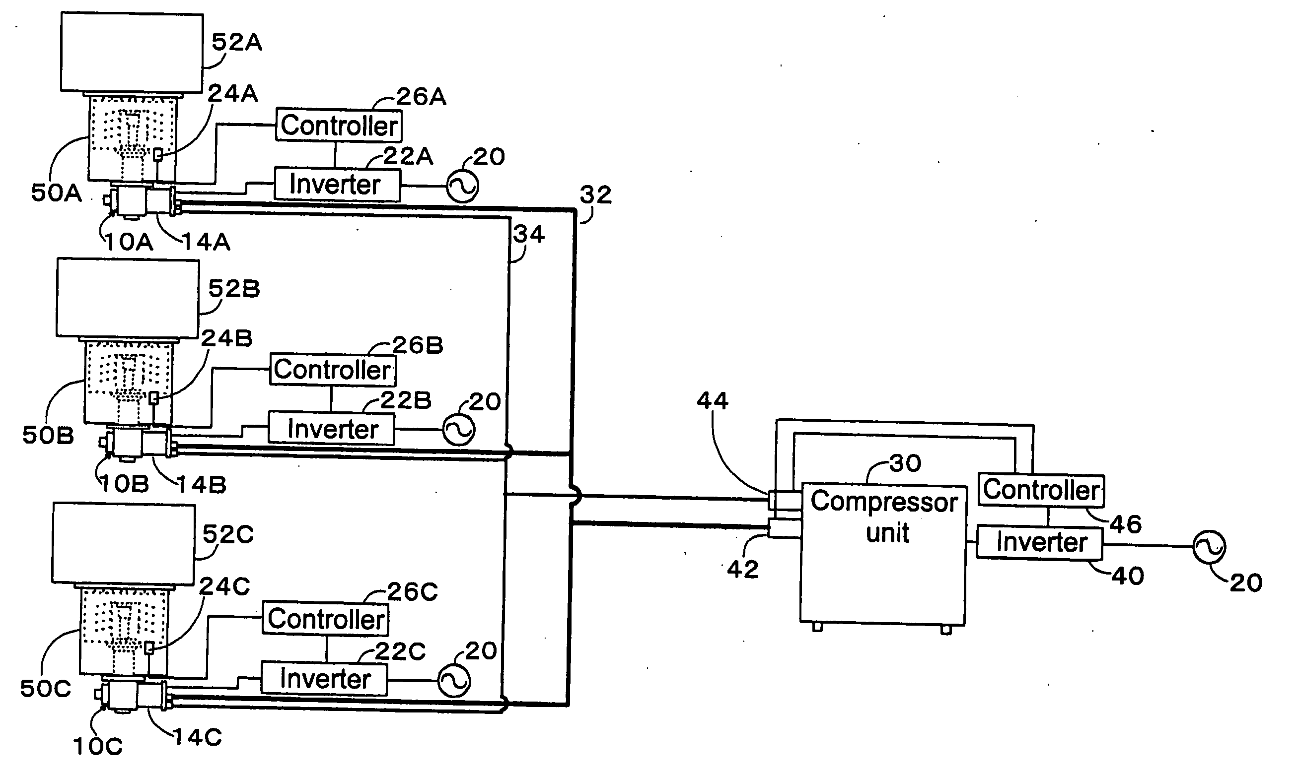
[0041] The present embodiment, as shown in FIG. 4, is formed by applying the present invention to the case where a single compressor unit 30 is used to run refrigerator units 10A, 10B, and 10C of three second-stage G-M cycle refrigerators. Similar to the first embodiment, the refrigerator units 10A, 10B, and 10C are provided with inverters 22A, 22B, and 22C, temperature sensors 24A, 24B, and 24C, as well as controllers 26A, 26B, and 26C, respectively.

[0042] The present embodiment further comprises: a second inverter 40 provided between the power source 20 and the compressor unit 30; pressure sensors 42 and 44 provided on a high-pressure gas line 32 and a low-pressure gas line 34 both serving as actuation gas pipelines and connecting the compressor unit 30 with the respective refrigerator units 10A, 10B, and 10C; and a second controller 46 which calculates a differential pressure between the high-pressure gas and the low-pressure ...


PUM

PropertyMeasurementUnit
Temperatureaaaaaaaaaa
Timeaaaaaaaaaa
Electrical conductoraaaaaaaaaa

Abstract

An inverter (22) is provided between a power source (20) and a suction/discharge valve driving motor (14) that controls cycle time of suction and discharge of a refrigerator unit (10). An output frequency of the inverter (22) is controlled in accordance with output of a sensor (24) that detects temperature of a thermal load portion (11) of the refrigerator unit (10). This enables temperature adjustment of individual refrigerators with a highly reliable method without using an electric heater.

Description

TECHNICAL FIELD [0001] The present invention relates to a cryogenic refrigerator, particularly to a cryogenic refrigerator capable of performing temperature adjustment and suitable for use with cryopump, superconductive magnet, cryogenic measuring apparatus, simple liquefaction apparatus or the like. BACKGROUND ART [0002] In general, a cryogenic refrigerator includes: an expansion type refrigerator unit accommodating a thermal accumulation material and has an expansion chamber located within the refrigerator; and a compressor unit containing a compressor main body. The refrigerator unit is installed within an apparatus or a container which is to be cooled to an extremely low temperature. Then, a high pressure refrigerant gas obtained through the compressor unit is fed to the refrigerator unit where the high pressure refrigerant gas is cooled by the thermal accumulation material and then expanded, followed by carrying out a further cooling step. Subsequently, a low pressure refrigera...

Claims


Application Information

Patent Timeline
IPC IPC(8): B01D8/00F25B49/00F25J1/00F04B37/08F25B9/14
CPCF04B37/08F25B9/14F25B2600/2515F25B2309/1428F25B2309/002
Inventor TANAKA, HIDEKAZU
Owner SUMITOMO HEAVY IND LTD
Why Eureka
Try Eureka