Intra-bronchial apparatus for aspiration and insufflation of lung regions distal to placement or cross communication and deployment and placement system therefor

a technology of aspiration and insufflation of lung regions, applied in the field of intrabronchial apparatus for aspiration and insufflation, can solve the problems of significantly altering the course of copd, not providing long-term relief, and insufficient reverse course, so as to facilitate selective drug delivery and reduce the total lung volume

Inactive Publication Date: 2006-05-18
ADLER MARK
View PDF99 Cites 26 Cited by
  • Summary
  • Abstract
  • Description
  • Claims
  • Application Information

AI Technical Summary

Benefits of technology

[0017] In its most essential aspect, the present invention is a selectively anchored intra-bronchial apparatus for placement and deployment into selected airways. When deployed, the apparatus creates a restriction of air flow to one or more targeted lung regions and achieves total lung volume reduction through a collapse or partial collapse of the targeted regions. The inventive apparatus includes an air flow valve having a through lumen that facilitates selective drug delivery concurrent with a lung volume reduction procedure. A novel specialized placement and deployment system may be employed and is also disclosed herein.

Problems solved by technology

The first improves the quality of life of the patient but is insufficient to reverse the course of the disease and does not provide relief in the long-term.
The second, pharmacotherapy, is largely palliative, and no studies support even the proposition that even early drug intervention can significantly alter the course of COPD.
And the third, surgery (i.e., lung volume reduction surgery, or LVRS), carries with it several risks even apart from those that attend any complicated thoracic surgery, though it is admittedly known to provide improvements in forced expiratory volume, a decreased total lung capacity, and improvement in lung function.
While difficult to generalize about a large body of art, the foregoing collection all relate to removable anchored lung volume reduction devices employed and methods for using the devices.

Method used


Image

  • Intra-bronchial apparatus for aspiration and insufflation of lung regions distal to placement or cross communication and deployment and placement system therefor
  • Intra-bronchial apparatus for aspiration and insufflation of lung regions distal to placement or cross communication and deployment and placement system therefor
  • Intra-bronchial apparatus for aspiration and insufflation of lung regions distal to placement or cross communication and deployment and placement system therefor

Examples


Embodiment Construction

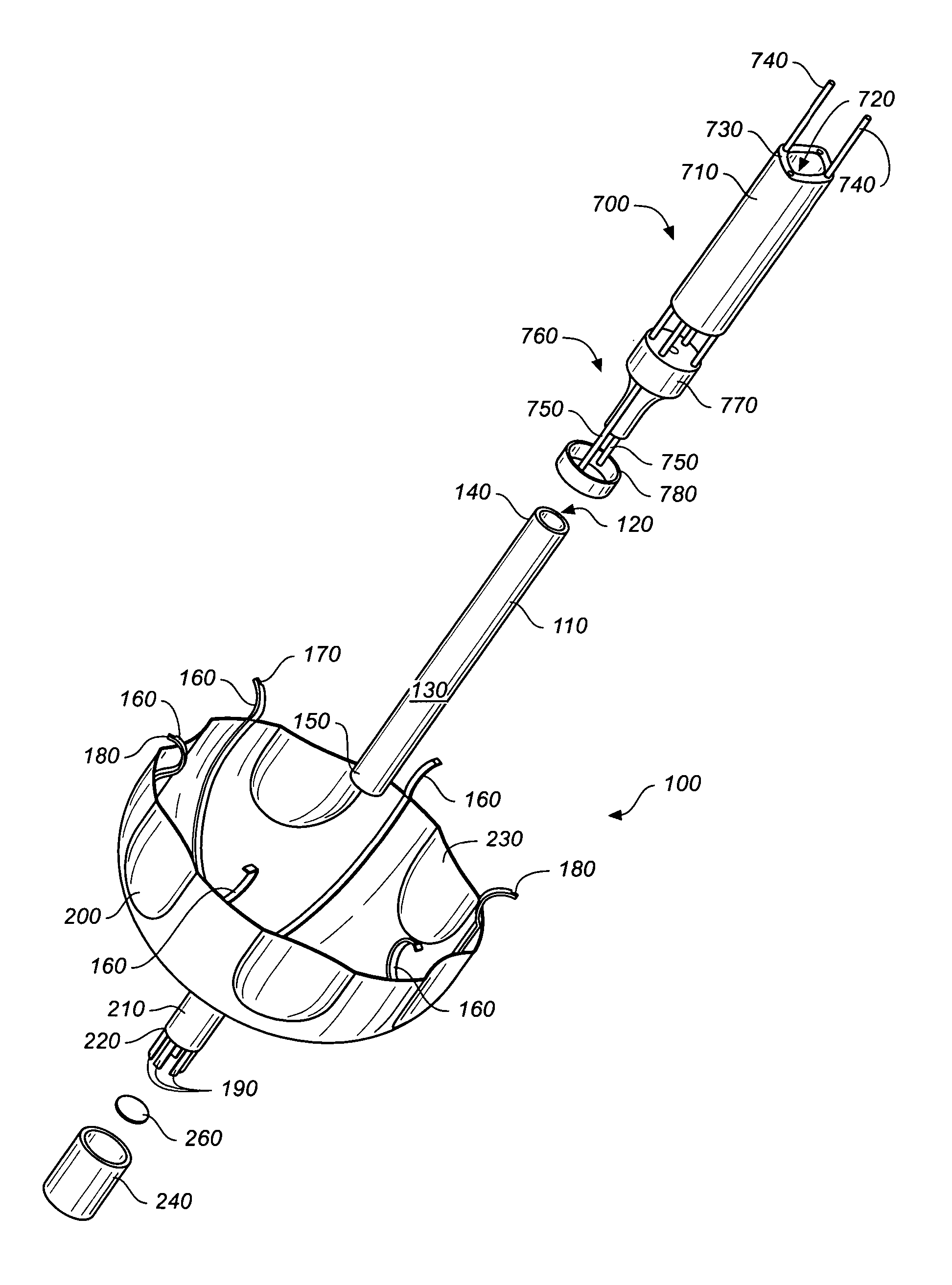
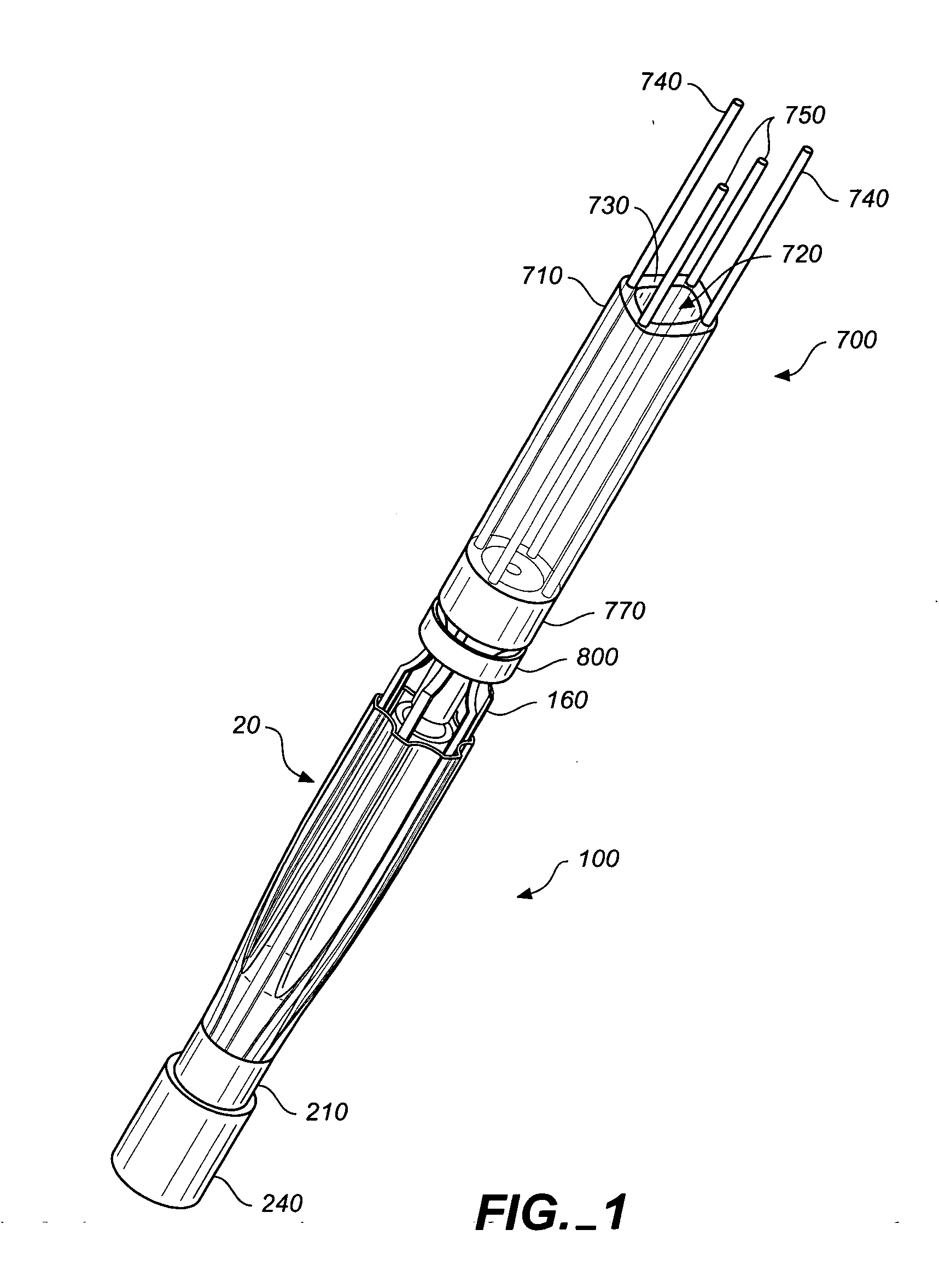
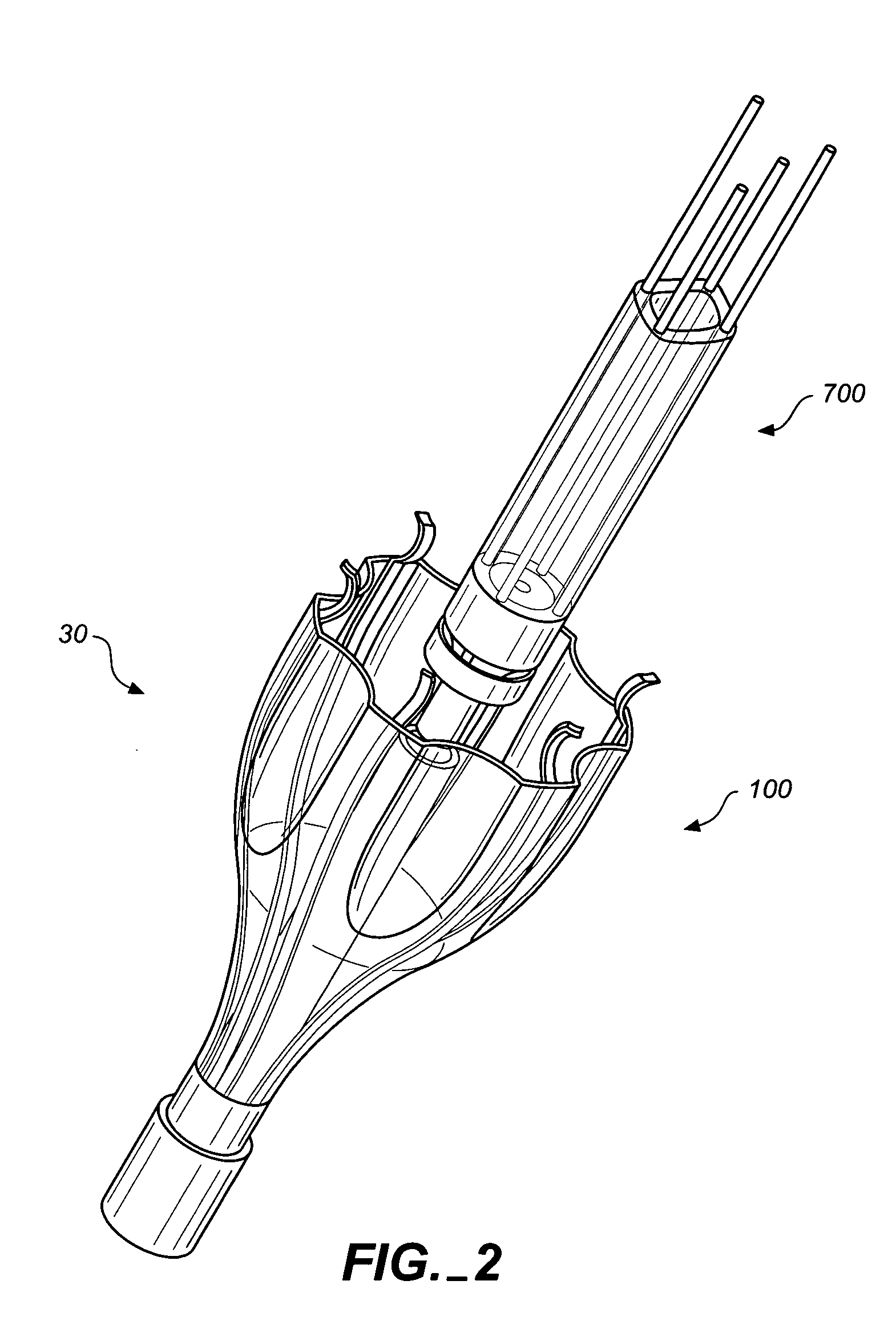
[0098] Referring to FIGS. 1 through 12C, wherein like reference numerals refer to like components in the various views, there is illustrated a new and improved intra-bronchial apparatus for aspiration or insufflation of lung regions distal to the apparatus placement or air passageway cross-communication. The air flow control valve portion apparatus is generally denominated 100 herein, while the deployment and placement system device is generally denominated 700.

[0099]FIGS. 1-8D illustrate a first preferred embodiment of the air flow control valve portion of the present invention. These views collectively show that the valve comprises a center tube 110 having a central lumen 120, an outside surface 130, an upper portion 140, and a lower portion 150. The valve further includes a plurality of resilient, arcuate strut arms 160, each having an upper arcuate portion 170 with a tip 180 shaped for anchoring the valve on the interior lumen wall of a body cavity, duct, vessel, or passageway....


PUM


Abstract

An anchored intra-bronchial apparatus for placement and deployment into selected airways and a method for using the same. When deployed, the apparatus creates a restriction of air flow to one or more targeted lung regions and achieves total lung volume reduction through a collapse or partial collapse of the targeted regions. The air flow valve of the apparatus includes a through lumen that permits drug delivery concurrent with lung volume reduction procedure

Description

CROSS REFERENCE TO RELATED APPLICATIONS [0001] The present application claims the benefit of the filing date of U.S. Provisional Patent Application, Ser. No. 60 / 629,451, filed Nov. 18, 2004.STATEMENT REGARDING FEDERALLY SPONSORED RESEARCH OR DEVELOPMENT [0002] Not applicable. REFERENCE TO A MICROFICHE APPENDIX [0003] Not applicable. TECHNICAL FELD [0004] The present invention relates generally to a method and apparatus for treatment of certain pulmonary diseases, more particularly to a bronchial obstruction apparatus, which may be either a plug or a uni-or bi-directional valve, and a deployment and placement system adapted for the novel apparatus. Still more particularly, the present invention is an intra-bronchial apparatus for the aspiration and / or insufflation of lung regions distal to placement of the apparatus and to cross-communication from other airways to other lung regions. The inventive apparatus is particularly well-adapted for the delivery of pharmacological agents and / o...

Claims


Application Information

Patent Timeline
Patent Type & Authority Applications(United States)
IPC IPC(8): A62B9/06A61M16/00
CPCA61B17/12022A61B17/12104A61B17/12172A61B2017/242A61M16/04A61M16/0434A61M16/0447
Inventor ADLER, MARK
Owner ADLER MARK
Why Eureka
Try Eureka